Single-winding forward and reverse excitation auxiliary power supply circuit

An auxiliary power supply, forward and flyback technology, applied in the direction of electrical components, electric variable adjustment, instruments, etc., can solve the problems of insufficient power supply of products, large transient energy consumption, and reduced product reliability, so as not to affect product reliability, The effect of simple circuit structure

Pending Publication Date: 2019-11-05
MORNSUN GUANGZHOU SCI & TECH
View PDF0 Cites 4 Cited by
  • Summary
  • Abstract
  • Description
  • Claims
  • Application Information

AI Technical Summary

Problems solved by technology

[0007] The purpose of the present invention is to provide a single-winding forward and flyback auxiliary power supply circuit without increasing the difficulty of transformer design or reducing product reliability, so as to solve the problem of insufficient power supply of products due to large transient energy consumption

Method used


Image

  • Single-winding forward and reverse excitation auxiliary power supply circuit
  • Single-winding forward and reverse excitation auxiliary power supply circuit
  • Single-winding forward and reverse excitation auxiliary power supply circuit

Examples


no. 1 example

[0028] A single-winding forward and flyback auxiliary power supply circuit includes a forward energy storage module, a forward voltage stabilizing module, a flyback energy storage module, and a flyback voltage stabilizing module. The forward energy storage module and the flyback energy storage module share a secondary auxiliary winding. When the winding is forward, the energy storage element inside the module is charged through the forward energy storage module; when the winding is flyback, the energy storage element inside the module is charged through the flyback energy storage module. The forward energy storage module outputs a forward voltage, and the flyback energy storage module outputs a flyback voltage.

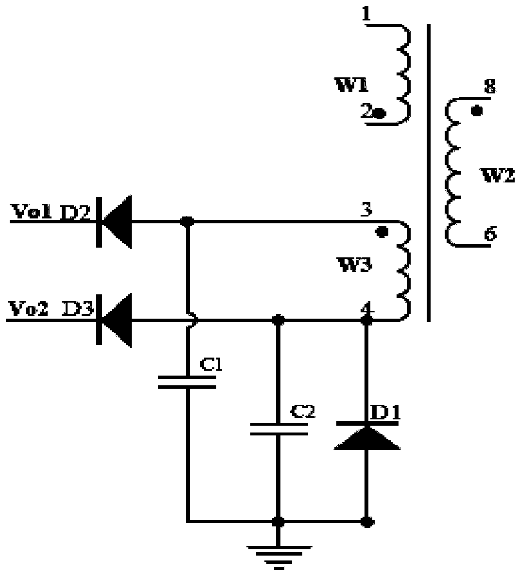
[0029] Such as image 3 It is the schematic circuit diagram of the first embodiment of the present invention, and the circuit structure of each module is as follows:

[0030] The flyback energy storage module includes a first energy storage capacitor C1, a third aux...

no. 2 example

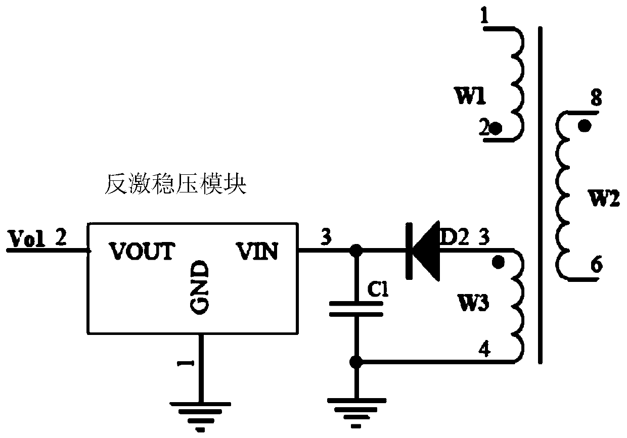
[0035] Such as Figure 4 As shown, it is the working principle diagram of the second embodiment. Compared with the first embodiment, the difference is that in this embodiment, the output terminal of the forward energy storage module is connected to the forward voltage regulator module to output a stable voltage, and the flyback The output end of the energy storage module is connected to the flyback regulator module to output a stable voltage. In the first embodiment, a straight-through wire is used for direct output.

[0036] Both the forward voltage stabilizing module and the flyback stabilizing module can use a linear voltage stabilizing circuit. Such as Figure 8 , the linear regulator module includes a first switch tube Q1 of an N-channel MOS transistor, a first resistor R1, a first voltage regulator tube Z1, a first input voltage Vin, and a first output voltage Vo. The first input voltage Vin is connected to the drain of the first switch tube, one end of the first resi...

no. 3 example

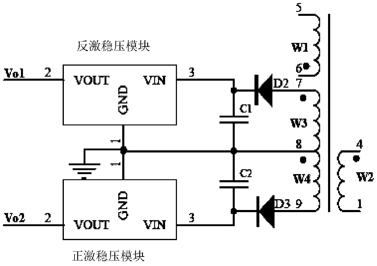
[0039] Such as Figure 5 Shown is the working principle diagram of the third embodiment. Compared with the second embodiment, the difference is that the output terminals of the two voltage stabilizing modules are connected in parallel to output a stable voltage. The working principle of realizing the auxiliary power supply of the forward and flyback windings in this embodiment is the same as that in the second embodiment, and will not be repeated here.


PUM


Abstract

The invention discloses a single-winding forward and reverse excitation auxiliary power supply circuit, and the circuit is characterized in that the device comprises a forward excitation energy storage module, a forward excitation voltage stabilization module, a reverse excitation energy storage module and a reverse excitation voltage stabilization module; the forward excitation energy storage module and the reverse excitation energy storage module share one secondary auxiliary winding; when the winding is in forward excitation, an energy storage element in the module is charged through the forward excitation energy storage module, and the forward excitation energy storage module outputs a forward excitation voltage. When the winding performs the reverse excitation, the reverse excitationenergy storage module charges energy to the energy storage element in the module, and the reverse excitation energy storage module outputs the reverse excitation voltage. According to the invention, the sufficient energy supply can be provided at the moment when the chip is started; the single-winding forward and reverse excitation auxiliary power supply is used, so that the transformer design difficulty and the product design difficulty are not influenced; the circuit is simple in structure and does not influence product reliability.

Description

technical field [0001] The circuit of the invention relates to the field of switching power supplies, in particular to a circuit using an auxiliary winding for auxiliary power supply. Background technique [0002] In the field of switching power supplies, the flyback topology and its extended topology are very popular and practical. The development of this type of design is of great significance to product upgrades. [0003] In this type of design, in the prior art, the auxiliary winding is often used to supply power to the main control IC, that is, when the product is working normally, the power supply energy of the main control IC is obtained from the auxiliary winding. But when the product is started, because the auxiliary winding has no energy temporarily, it is necessary to supply power to the main control IC through other methods, and the commonly used technology is to supply power to the main control IC through a startup circuit. For this type of product, the power ...

Claims


Application Information

Patent Timeline
Patent Type & Authority Applications(China)
IPC IPC(8): H02M3/335H02M1/36H02M3/07
CPCH02M1/36H02M3/07H02M3/33523
Inventor 尹向阳王小亮陈必宏
Owner MORNSUN GUANGZHOU SCI & TECH
Why Eureka
Try Eureka