Punching device for agricultural planting

A punching device and agricultural technology, applied in agriculture, planting methods, watering devices, etc., can solve problems such as poor punching effect and affect user work efficiency, and achieve the effect of convenient movement, simple structure, and improved work efficiency

Inactive Publication Date: 2019-11-08
黄萍
View PDF6 Cites 1 Cited by
  • Summary
  • Abstract
  • Description
  • Claims
  • Application Information

AI Technical Summary

Problems solved by technology

[0003] However, due to the relatively simple structure of the punching device, the punching device has a poor punching effect on hard ground, so that the user needs to repeatedly punch holes, which affects the user's work efficiency.

Method used


Image

  • Punching device for agricultural planting
  • Punching device for agricultural planting
  • Punching device for agricultural planting

Examples


Embodiment 1

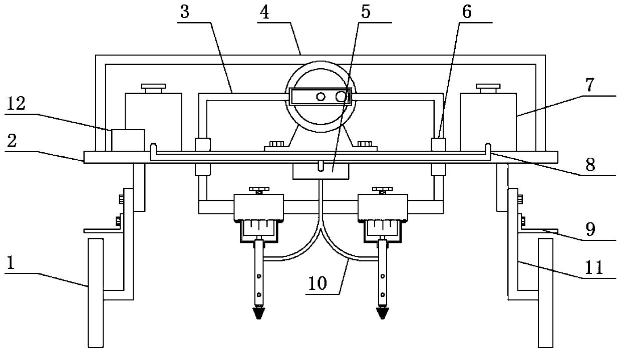
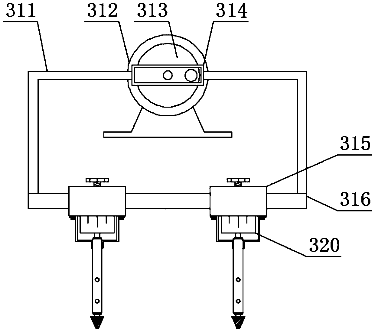
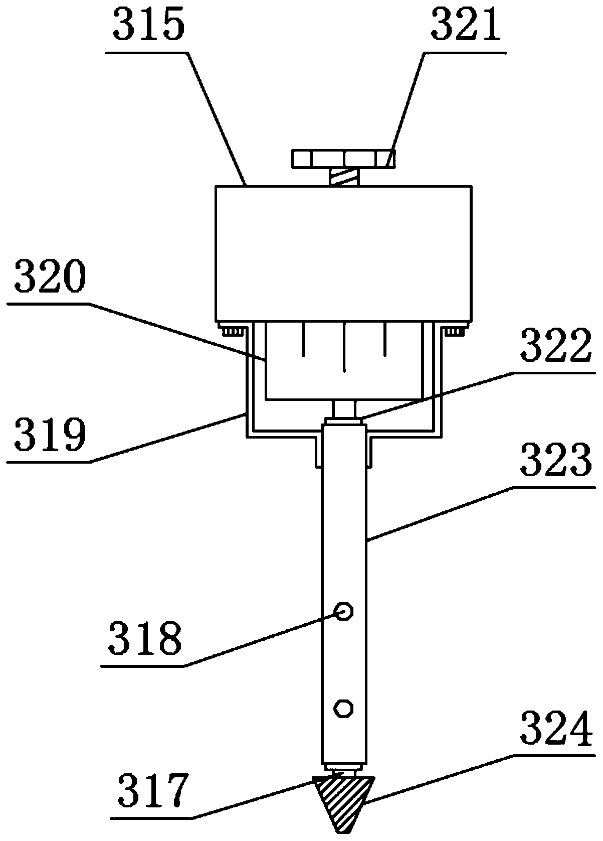
[0020] see Figure 1-Figure 4 , the present invention provides a technical solution: a punching device for agricultural planting, comprising a first support plate 2, a ground wheel 1 is provided below the first support plate 2, and two ends of the lower surface of the first support plate 2 are provided with The connector 11 corresponding to the ground wheel 1, the battery 12 is arranged on one end of the upper surface of the first support plate 2, and the punching mechanism 3 is arranged above the first support plate 2, and the punching mechanism 3 includes a first driving motor 312, The output end of the first drive motor 312 is provided with the second transmission member 313, the use of the second transmission member 313 is prior art, the bottom of the first drive motor 312 is provided with the second support plate 316, the top of the second support plate 316 A third transmission member 314 corresponding to the second transmission member 313 is provided, the connection betw...

Embodiment 2

[0026] On the basis of Embodiment 1, in order to make the punching device move more conveniently, in this embodiment, preferably, one end of the upper surface of the first support plate 2 is provided with a handrail 4, and the bottom end of the handrail 4 is connected to the first support. The plate 2 is fixedly connected by welding, and the punching device is pushed to move through the mutual cooperation of the handrail 4 and the ground wheel 1 during use, so that the punching device is more convenient to move;

[0027] In order to enrich the functions of the punching device, in this embodiment, preferably, the bottom end of the connector 11 is provided with a scraper 9 corresponding to the ground wheel 1, the scraper 9 is an "L" shaped structure, and the scraper 9 It is fixedly connected with the connecting piece 11 by screws. When a large amount of dirt and other sundries adhere to the ground wheel 1, the scraper 9 scrapes off the sundries on the ground wheel 1 to prevent th...


PUM


Abstract

The invention discloses a punching device for agricultural planting and belongs to the technical field of agricultural machinery. The punching device comprises a first supporting plate, land wheels are arranged below the first supporting plate, connection members corresponding to the land wheels are arranged at two ends of the lower surface of the first supporting plate, a storage battery is arranged at one end of the upper surface of the first supporting plate, a punching mechanism is arranged above the first supporting plate and comprises a first driving motor, a second transmission member is arranged at the output end of the first driving motor, a second supporting plate is arranged below the first driving motor, and a third transmission member corresponding to the second transmission member is arranged above the second supporting plate. The punching device is simple in structure and convenient to use; when the punching device is in use, the punching device is enabled to easily punch even on a hard ground through mutual cooperation of the first driving motor and the second driving motor, so that a user does not need repeat punching, and working efficiency of the user is improvedeffectively.

Description

technical field [0001] The invention belongs to the technical field of agricultural machinery, and in particular relates to a punching device for agricultural planting. Background technique [0002] Chinese patent (publication number CN208581465U) discloses a drilling device for agricultural planting, including a working platform, an electric telescopic rod is provided at the bottom of the top plate, a drive motor is provided at the bottom of the electric telescopic rod, and the outer wall of the rotating shaft is provided with Spiral loose soil sheet, the working platform is provided with a hole, the right side of the working platform is provided with a telescopic device, the right side of the telescopic device is provided with a sleeve, and the inner cavity of the sleeve is inserted with a limit rod. A compression spring is sleeved on the outer wall of the limit rod, and a pressing plate is arranged on the top of the limit rod. [0003] However, due to the relatively simp...

Claims


Application Information

Patent Timeline
Patent Type & Authority Applications(China)
IPC IPC(8): A01C5/04A01G25/09
CPCA01C5/04A01G25/09
Inventor 不公告发明人
Owner 黄萍
Why Eureka
Try Eureka