Coalescence filter core structure and filtering device

A technology of coalescing and filter element, which is applied in the field of coalescing filter element structure and filter device, can solve the problems that the processing capacity cannot meet the use requirements, the filtration efficiency decreases, and the pressure drop of the filter element increases, so as to improve the pressure drop of the filter element. Operating costs and the effect of extending the service life

Pending Publication Date: 2019-11-08
CHINA UNIV OF PETROLEUM (BEIJING)
View PDF0 Cites 9 Cited by
  • Summary
  • Abstract
  • Description
  • Claims
  • Application Information

AI Technical Summary

Problems solved by technology

Especially in multiphase flow conditions, when the working conditions change greatly, the liquid content and dust content in the gas fluctuate greatly
When it is in the working condition of high-concentration impurities and large-size droplets, the processing capacity of the coalescing filter element in the prior art cannot meet the use requirements, and the impurities in the gas will be congested on the intake side of the coalescing filter element, blocking the filter element, resulting in The pressure drop of the filter element rises sharply, so that the droplets that have been captured by the coalescing filter element enter the downstream airflow again under the drive of the airflow, causi

Method used


Image

  • Coalescence filter core structure and filtering device
  • Coalescence filter core structure and filtering device
  • Coalescence filter core structure and filtering device

Examples


Embodiment Construction

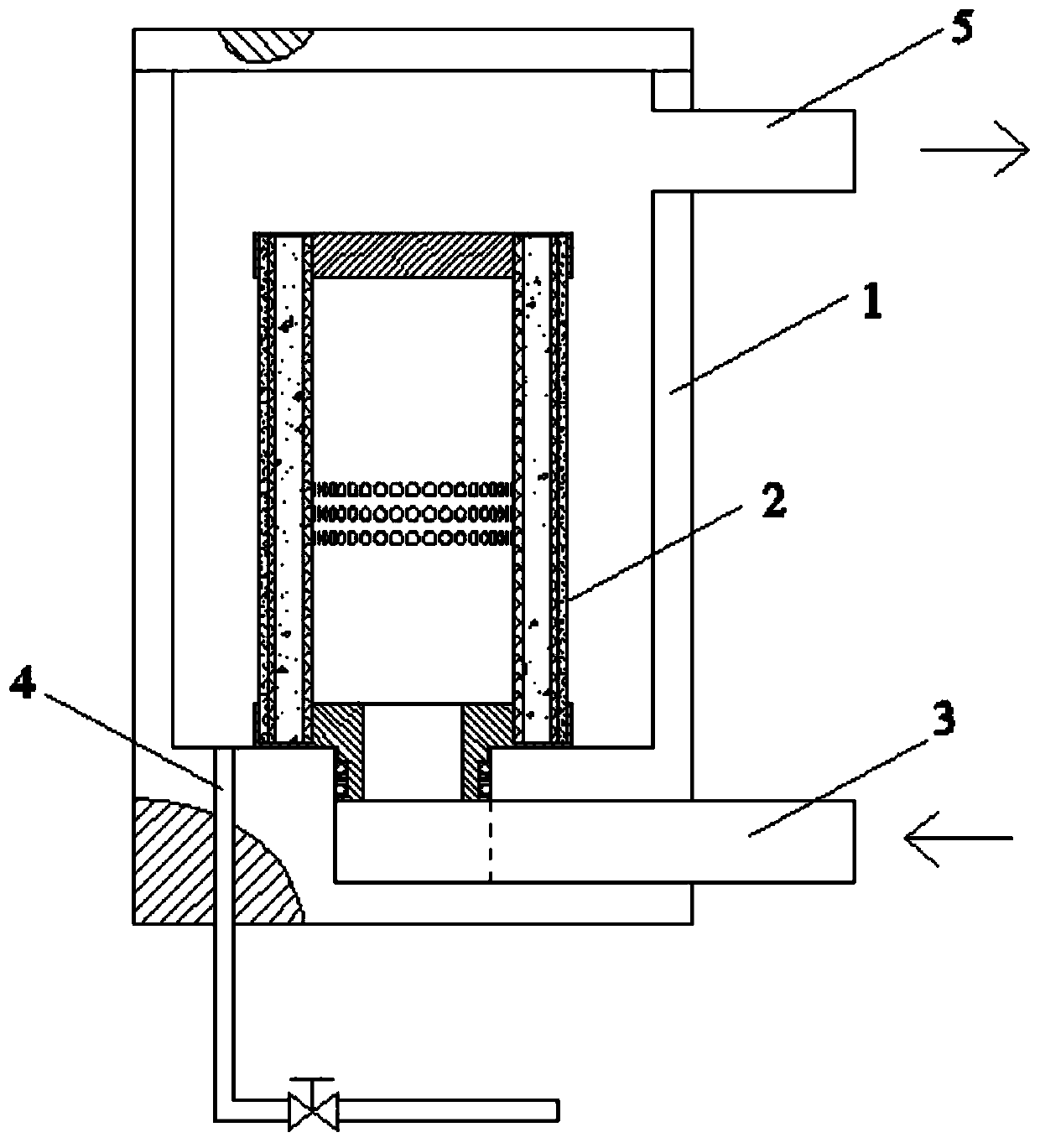
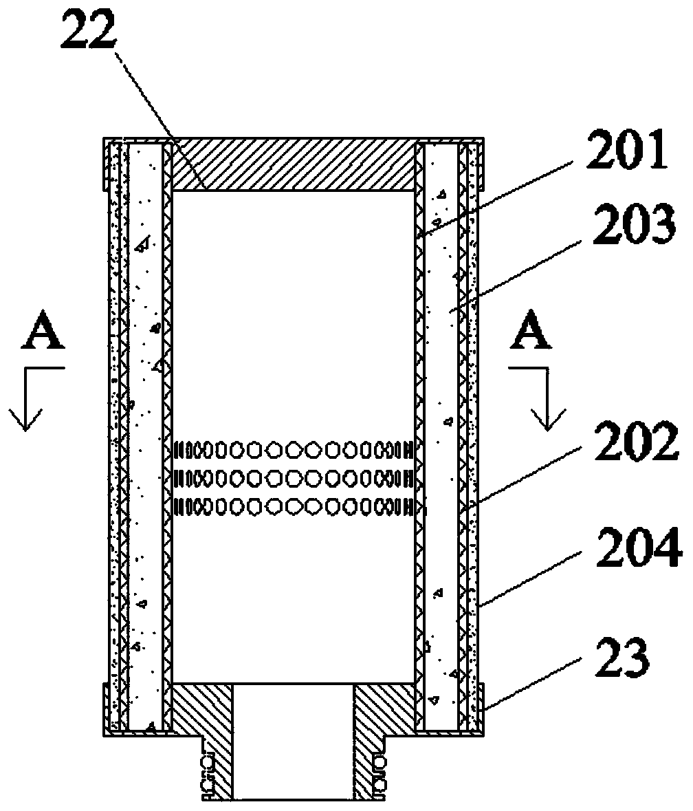
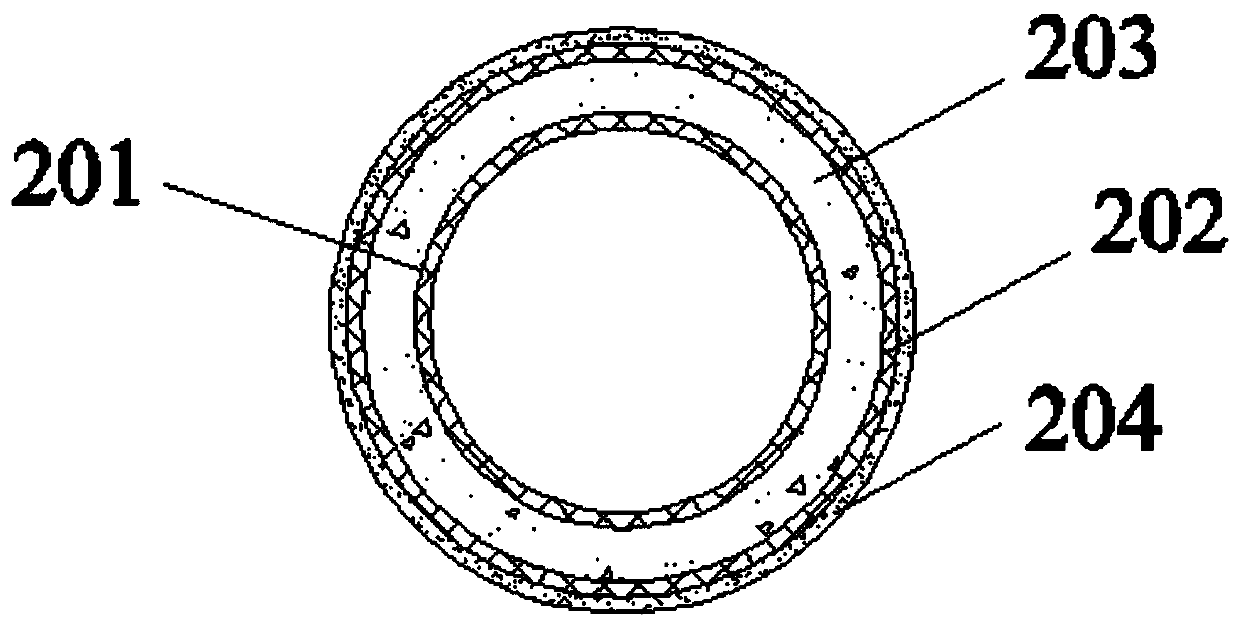
[0039] The technical solutions of the present invention will be described in detail below in conjunction with the accompanying drawings and specific embodiments. It should be understood that these embodiments are only used to illustrate the present invention and not to limit the scope. After reading the present invention, those skilled in the art will understand the present invention Modifications of various equivalent forms fall within the scope defined in the present application.

[0040] It should be noted that when an element is referred to as being “disposed on” another element, it may be directly on the other element or there may also be an intervening element. When an element is referred to as being "connected to" another element, it can be directly connected to the other element or intervening elements may also be present. As used herein, the terms "vertical", "horizontal", "upper", "lower", "left", "right" and similar expressions are for the purpose of illustration on...


PUM

PropertyMeasurementUnit
Diameteraaaaaaaaaa
Fiber diameteraaaaaaaaaa

Abstract

The invention provides a coalescence filter core structure and a filtering device. The coalescence filter core structure comprises: a first inner frame, which is equipped with at least one internal drainage flow channel and an air inlet at the bottom, and encircles a to-be-filtered space communicated with the air inlet; a pre-filter layer and a liquid collection layer that are sleeved outside thefirst inner frame in order; a second inner frame sleeved outside the liquid collection layer, with a clearance space being formed between the liquid collection layer and the second inner frame and being communicated with the internal drainage flow channel; an outer frame sleeved outside the second inner frame, with a coalescence space formed between the second inner frame and the outer frame; a filter core disposed in the coalescence space; an upper end cover, which seals at least the end of the to-be-filtered space; and a lower end cover, which is equipped with an opening for inserting into the first inner frame, and is in detachable connection with the bottom of the first inner frame. The coalescence filter core structure and the filtering device provided by the invention can prolong theservice life of the coalescence filter core.

Description

technical field [0001] The invention relates to the field of gas-liquid filtration, in particular to a coalescing filter element structure and a filtering device. Background technique [0002] In long-distance natural gas transmission pipelines, natural gas generally contains solid and liquid impurities. The existence of these impurities will endanger the safety of pipeline equipment and compressor units. Therefore, it is necessary to install corresponding gas-liquid filtering devices such as coalescence filters to remove of impurities. The core component of the coalescing filter used to remove tiny droplets in natural gas is a coalescing filter element, which requires high filtration accuracy and is mainly used to remove droplet particles below 1 μm. [0003] Filter element structure and filtering device in the prior art please refer to Figure 1 to Figure 3 . Such as Figure 1 to Figure 3 As shown, the coalescing filter element 2 is supported by the second inner skeleton...

Claims


Application Information

Patent Timeline
IPC IPC(8): B01D46/30B01D46/00
CPCB01D46/0002B01D46/30
Inventor 常程姬忠礼刘震吴小林刘宇峰
Owner CHINA UNIV OF PETROLEUM (BEIJING)
Why Eureka
Try Eureka