Proofreading type adhesive dispensing device for electronic manufacturing

A dispensing device and electronic technology, which is applied to the device for coating liquid on the surface, the pretreatment surface, the coating, etc., can solve the problems of inability to check the dispensing position, slow curing speed, low processing efficiency, etc., to improve the solidification. The effect of speed, improving accuracy, and quick proofreading

Pending Publication Date: 2019-11-08
NANJING COLLEGE OF INFORMATION TECH
View PDF1 Cites 10 Cited by
  • Summary
  • Abstract
  • Description
  • Claims
  • Application Information

AI Technical Summary

Problems solved by technology

[0003] The existing dispensing device cannot correct the dispensing position, and relies on the glue itself to solidify, the curing speed is slow, and the processing efficiency is low

Method used


Image

  • Proofreading type adhesive dispensing device for electronic manufacturing
  • Proofreading type adhesive dispensing device for electronic manufacturing
  • Proofreading type adhesive dispensing device for electronic manufacturing

Examples


Embodiment 1

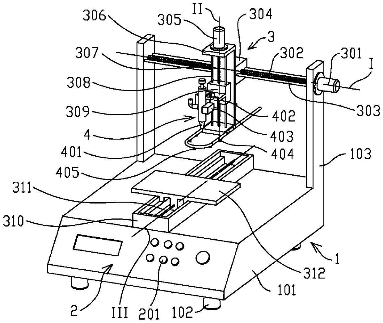
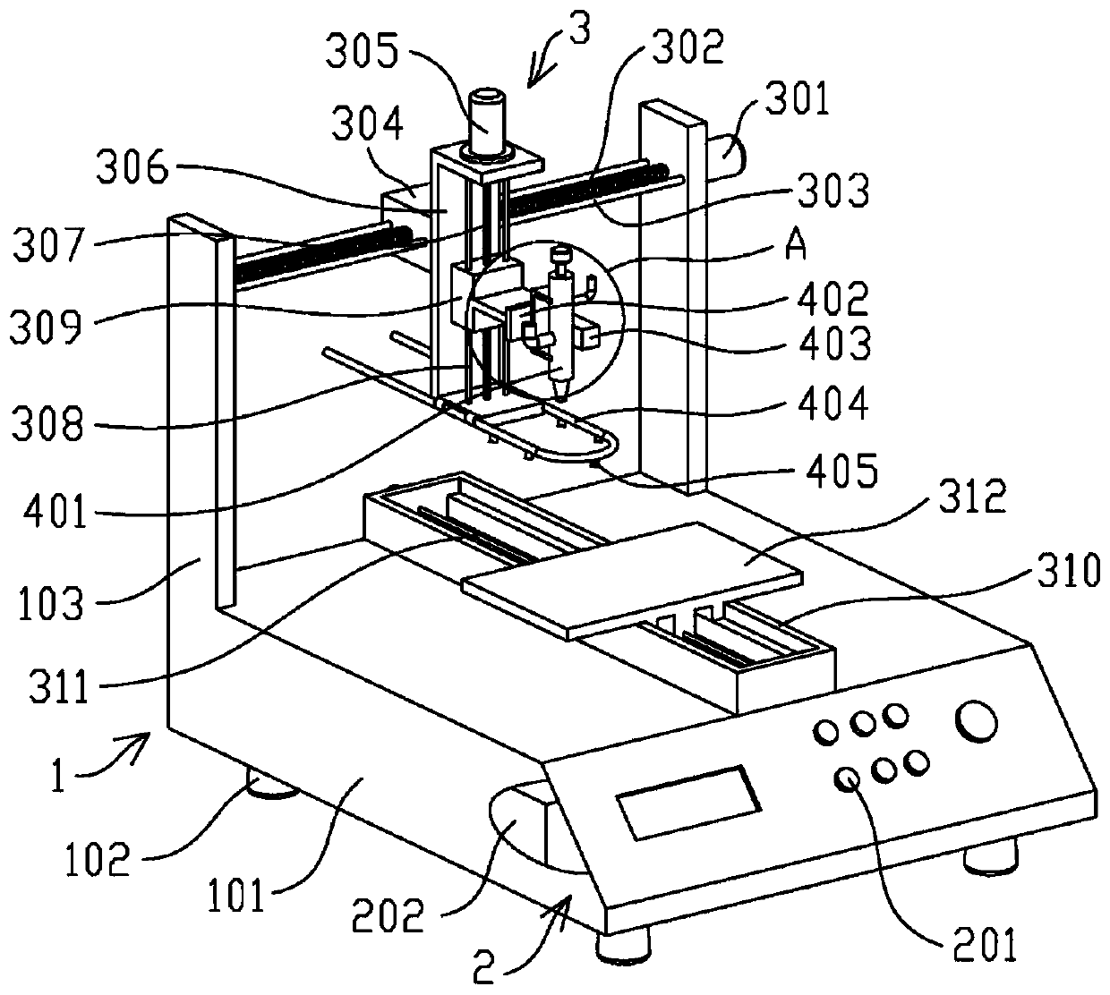
[0045] Such as Figures 1 to 6 As shown, a proofreading dispensing device for electronic manufacturing includes: a fixing mechanism 1 , a control mechanism 2 , a feeding mechanism 3 and a glue dispensing mechanism 4 .

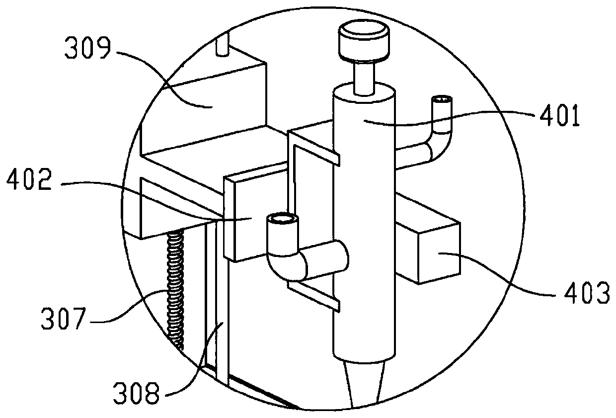
[0046] The fixing mechanism 1 has a base 101, the feeding mechanism 3 has a stage 312 and a second movable block 309, and the dispensing mechanism 4 has a dispensing valve 401 and a dispensing valve 401 arranged on the second movable block 402. The calibrator 403 is used to calibrate the position of the dispensing valve 401 and the workpiece, and the calibrator 403 is fixed on one side of the dispensing valve 401 . The glue dispensing mechanism 4 also has a glue storage cylinder and a glue pump, and the glue in the glue storage cylinder is supplied to the glue dispensing valve 401 through the glue pump. The feeding mechanism 3 can drive the second movable block 309 to move relative to the object stage 312 in space under the control of the control mechanism 2 ,...

Embodiment 2

[0064] The difference from Embodiment 1 is that in this embodiment, the object stage 312 is fixed, and the second movable block 309 moves in a three-dimensional space driven by the feeding mechanism 3, so as to meet the glue dispensing requirements. A specific structure to achieve the above purpose, the feed mechanism 3 can be a three-axis manipulator, for example, a three-axis manipulator is disclosed in the patent text with the application number "201910033805.9", and only the suction cup assembly needs to be replaced with a point The glue mechanism 4 can realize the purpose of spatial movement, so details are not repeated here.


PUM


Abstract

The invention discloses a proofreading type adhesive dispensing device for electronic manufacturing. A fixed mechanism, a control mechanism, a feeding mechanism and an adhesive dispensing mechanism are included, wherein the fixed mechanism is provided with a base; the feeding mechanism is provided with an object carrying table and a second movable block; the adhesive dispensing mechanism is provided with an adhesive dispensing valve arranged on the second movable block and a calibrator used for calibrating the positions of the adhesive dispensing valve and a workpiece; the calibrator is fixedly arranged on one side of the adhesive dispensing valve; the feeding mechanism can be controlled by the control mechanism to drive the second movable block to move in the space relative to the objectcarrying table; and the adhesive dispensing mechanism can be driven by the control mechanism to perform adhesive dispensing operation. According to the proofreading type adhesive dispensing device forelectronic manufacturing, infrared ray emitted out of an infrared distance measuring sensor is irradiated onto an electronic element, the position of the electronic element is fast proofread, the adhesive dispensing precision is improved, and meanwhile the distance between the adhesive dispensing valve and the electronic element is convenient to adjust.

Description

technical field [0001] The invention belongs to the technical field of glue dispensing devices, in particular to a proofreading type glue dispensing device for electronic manufacturing. Background technique [0002] Electronic components are components of electronic components and electric small machines and instruments. They are often composed of several parts and can be used in similar products. They often refer to certain parts in industries such as electrical appliances, radios, and instruments, such as capacitors and transistors. The general term for sub-components such as hairsprings, hairsprings, etc., common ones are diodes, etc. Dispensing devices are required in the manufacture of electronic components. [0003] The existing dispensing device cannot correct the dispensing position, and relies on the solidification of the glue itself, the curing speed is slow, and the processing efficiency is low. Contents of the invention [0004] The purpose of the present inve...

Claims


Application Information

Patent Timeline
Patent Type & Authority Applications(China)
IPC IPC(8): B05C5/02B05C11/00B05C9/12B05C13/00B05D3/04
CPCB05C5/0208B05C9/12B05C11/00B05C13/00B05D3/0406
Inventor 李建林李方方武文扬
Owner NANJING COLLEGE OF INFORMATION TECH
Why Eureka
Try Eureka