A multi-station hardware machining flanging mold

A technology for flanging molds and hardware, applied in metal processing equipment, forming tools, manufacturing tools, etc., can solve the problems of inconsistent curvature radius at the bending point of plate-shaped parts and excessive heating of the surface of plate-shaped parts.

Active Publication Date: 2020-07-07
海安时新机械制造有限公司
View PDF7 Cites 0 Cited by
  • Summary
  • Abstract
  • Description
  • Claims
  • Application Information

AI Technical Summary

Problems solved by technology

[0006] Aiming at the problems in the prior art, the purpose of the present invention is to provide a multi-station hardware machining flanging mold, which solves the technical problems of excessive heating of the surface of the plate-shaped part and inconsistent curvature radii at the bending part of the plate-shaped part

Method used


Image

  • A multi-station hardware machining flanging mold
  • A multi-station hardware machining flanging mold
  • A multi-station hardware machining flanging mold

Examples


Embodiment 1

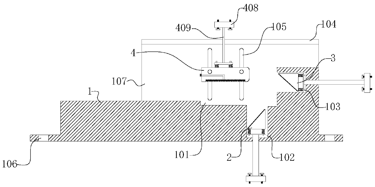
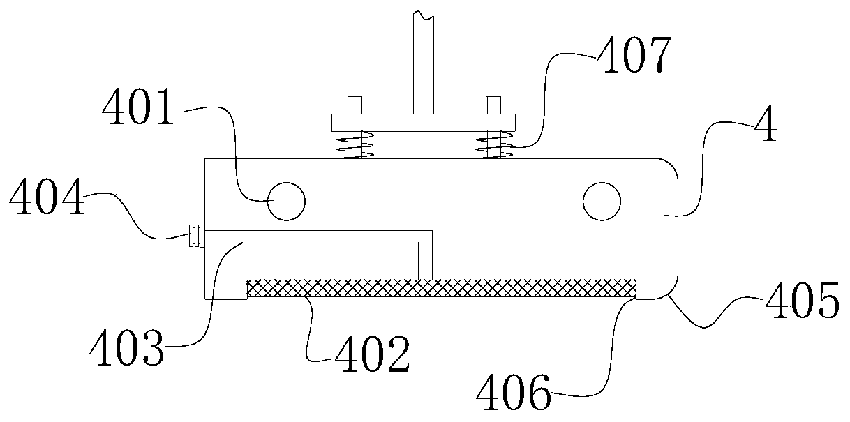
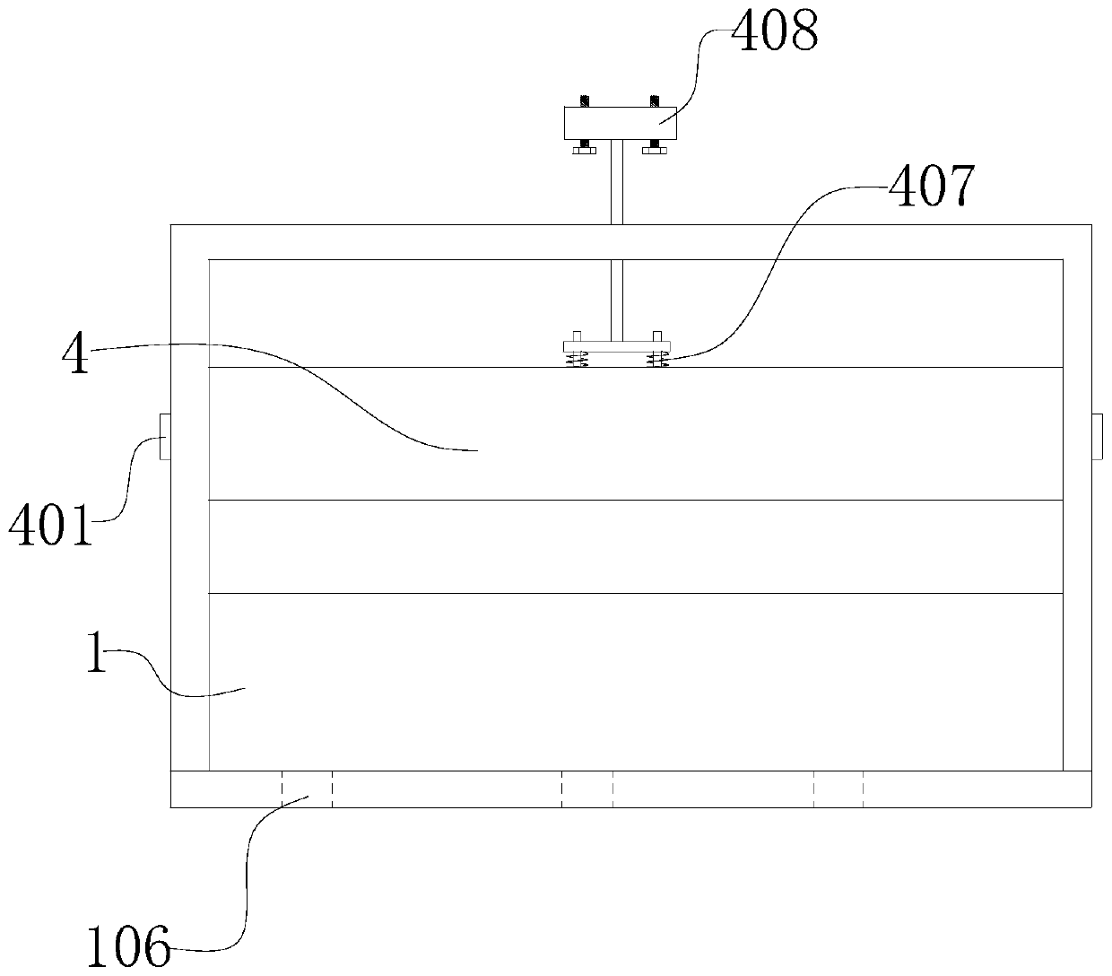
[0033] see figure 1 and figure 2 , is a schematic diagram of the overall structure of a multi-station hardware machining flanging die; including: a lower die base 1, a first punch 2, a second punch 3, an upper die base 4, and the upper die base 4 is set in a square shape Block shape, the two end faces of the upper mold base 4 are provided with bosses 401, and the bosses 401 are set as cylindrical, the upper mold base 4 is arranged above the lower mold base 1, and the lower mold base 1 is set as a square shape, and the square One end of the block is provided with a boss, the two side walls of the lower mold base 1 are provided with support plates, the support plate is provided with a slide hole 105, the top of the support plate is provided with a top support plate, and the boss 401 is embedded in the slide hole 105 ;

[0034] Wherein, the inside of the upper die base 4 is provided with an oil cavity 403, one end of the oil cavity is connected to the side wall of the upper di...

Embodiment 2

[0043] see Figure 1-5 , is a structural schematic diagram of another multi-station hardware machining flanging mold. This embodiment has the same content as the above-mentioned embodiment 1, and the same will not be described in this embodiment. The specific differences in:

[0044] The top of lower mold base 1 is provided with positioning groove 101, and the contour shape of positioning groove 101 is set as the same as the outer contour shape of hardware, and the bottom of positioning groove 101 is provided with first sinking groove 102, and first sinking groove 102 is made as square Groove, the first punch 2 is provided in the groove of the first sinking groove 102, the side wall of the boss is provided with the second sinking groove 103, the second sinking groove 103 is made as a square groove, and the groove of the second sinking groove 103 is provided with There are 2nd punches 3.

[0045] The first punch 2 is set as a triangular block structure, and the inclined surfa...


PUM


Abstract

The invention discloses a multi-station hardware machining flanged die, and relates to the technical field of die processing equipment. The multi-station hardware machining flanged die comprises a lower die base, a first punch, a second punch and an upper die base; the upper die base is arranged to bein a square block shape; the end faces of the two ends of the upper die base are provided with protrusion columns; the upper die base is arranged above the lower die base; the lower die base is arranged to be in a square block shape, and one end of the square block shape is provided with a boss; and the two side walls of the lower die base are provided with support plates. An oil cavity is formed in the upper die base, one end of the oil cavity is connected with an oil cavity connector, the other end of the oil cavity is connected with a sponge block, when the upper die base is moved downwards anda plate-shaped part on the lower die base is clamped, the sponge block is attached to the surface of the plate-shaped part, oil temperature on the sponge block is conducted in the plate-shaped part, the temperature control effect on the plate-shaped part is achieved during punching, and the internal structural stability of the plate-shaped part after punching forming is improved.

Description

technical field [0001] The invention relates to the technical field of mold processing equipment, in particular to a multi-station hardware machining flanging mold. Background technique [0002] Hardware, also known as hardware accessories, refers to machine parts or components made of hardware, as well as some small hardware products. It can be used alone or as an auxiliary tool. Such as hardware tools, hardware parts, daily hardware, construction hardware and security supplies, etc. Most hardware products are not final consumer goods. Instead, it is used as ancillary products, semi-finished products, and tools used in the production process for industrial manufacturing. Only a small part of daily hardware products (accessories) are tools and consumer goods necessary for people's lives. [0003] At present, there are many hardware structures, such as thin plate-shaped parts, which are stamped and formed by molds during production to obtain the required structural shape....

Claims


Application Information

Patent Timeline
Patent Type & Authority Patents(China)
IPC IPC(8): B21D37/10B21D19/08
CPCB21D19/08B21D37/10
Inventor 吴振飞廉静
Owner 海安时新机械制造有限公司
Why Eureka
Try Eureka