AI technical title is built by Patsnap AI team. It summarizes the technical point description of the patent document.
A technology for cutting equipment and steel bars, which is applied in the field of steel bar cutting equipment, and can solve the problems of human operator's physical danger and low degree of automation.
Active Publication Date: 2019-11-08
王学凤
View PDF7 Cites 9 Cited by
Summary
Abstract
Description
Claims
Application Information
AI Technical Summary
This helps you quickly interpret patents by identifying the three key elements:
Problems solved by technology
Method used
Benefits of technology
Problems solved by technology
[0002] During the construction of bridges, it is often encountered that the program of cutting steel bars in batches has a low degree of automation, and too many manual operations will cause danger to the human body. This invention solves the above problems
Method used
Image
Click on the blue label to locate the original text in one second.
Reading with bidirectional positioning of images and text.
Examples
specific Embodiment approach 1
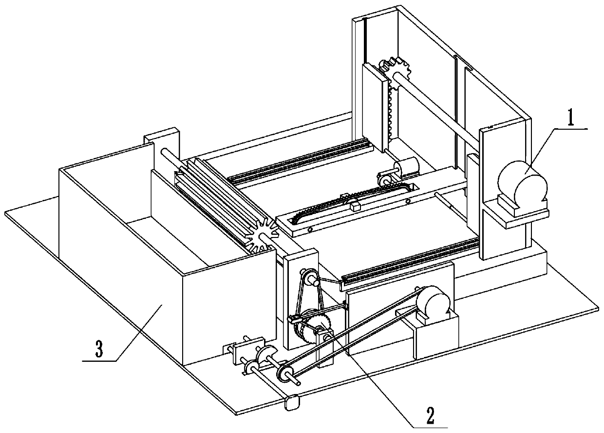
[0033] Combine below Figure 1-19 Describe this embodiment, a steel bar cutting equipment, including a cutting assembly 1, a feeding assembly 2 and a material box assembly 3, characterized in that: the feeding assembly 2 is connected to the cutting assembly 1, and the material The box assembly 3 is connected to the cutting assembly 1 .
specific Embodiment approach 2
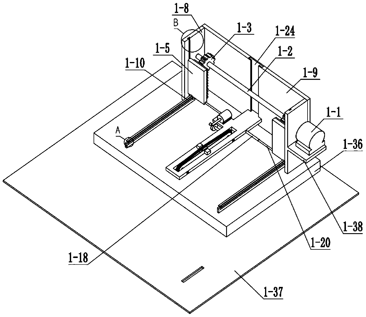
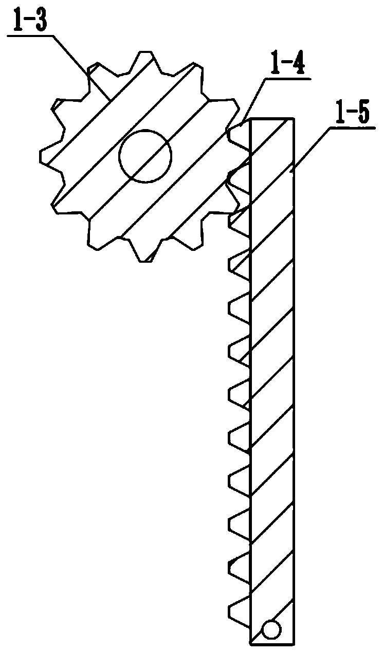
[0035] Combine below Figure 1-19 Describe this embodiment, this embodiment will further explain the first embodiment, the cutting assembly 1 includes a servo motor 1-1, a lifting shaft 1-2, a lifting gear 1-3, a lifting rack 1-4, and a lifting plate 1-5, lifting plate slide rail 1-6, lifting plate chute 1-7, side plate Ⅰ1-8, side plate Ⅱ1-9, lifting rod 1-10, spherical chute 1-11, ball head 1-12 , ball stud 1-13, ball stud lug 1-14, turret 1-15, fixed block 1-16, fixed frame 1-17, threaded slide 1-18, T-shaped hole 1-19, support Shaft 1-20, cutting frame chute Ⅰ1-21, cutting frame slide rail 1-22, cutting frame 1-23, cutting frame chute Ⅱ1-24, motor Ⅰ1-25, worm 1-26, worm gear 1-27, worm gear shaft 1-28, sprocket Ⅰ 1-29, chain Ⅰ 1-30, tensioning sprocket 1-31, tensioning sprocket shaft 1-32, sprocket Ⅱ 1-33, sprocket Ⅱ shaft 1-34 , cutting knife 1-35, cutting base plate 1-36, base plate 1-37 and motor support 1-38, servo motor 1-1 is connected with lift shaft 1-2, lift shaf...
specific Embodiment approach 3
[0037] Combine below Figure 1-19 Describe this embodiment, this embodiment will further explain Embodiment 1, the described feeding assembly 2 includes motor II 2-1, motor II shaft 2-2, slotted rotary block 2-3, slide bar 2-4, Slider Ⅰ 2-5, Slider Ⅰ chute 2-6, Support plate 2-7, Slider shaft 2-8, Connecting rod 2-9, Connecting rod shaft 2-10, Slider Ⅱ 2-11, Slider Ⅱ Chute 2-12, slider II connecting rod 2-13, puller 2-14, rocker 2-15, rocker shaft 2-16, rocker shaft bracket 2-17, gear shaft 2-18, dial Teeth 2-19, ratchet 2-20, ratchet shaft 2-21, sprocket III 2-22, chain II 2-23, sprocket IV 2-24, feeding shaft 2-25, feeding drum 2-26, feeding Shaft support 2-27, inclined plate 2-28, inclined plate support 2-29 and motor II support 2-30, motor II 2-1 rotates half a circle, servo motor 1-1 rotates one circle, motor II 2-1 and motor II shaft 2-2 phase connection, the motor II shaft 2-2 is connected with the slotted rotary block 2-3, the slotted rotary block 2-3 is slidingly co...
PUM
Abstract
The invention relates to the field of bridges, in particular to steel barcutting equipment. The steel barcutting equipment comprises a cutting combined body, a feeding combined body and a material box combined body. By means of the steel bar cutting equipment, the problems frequently encountered when a bridge is built that the automation degree of programs for cutting steel bars in batches is low, and danger is generated to human bodies by too much manual operation are solved. To-be-cut steel bars are put into a material box, a threaded sliding barrel is adjusted, a cutter blade slides in the axial direction of a supporting shaft, and the cutting length of the steel bars can be adjusted. The cutter blade moves reciprocatingly up and down so that the steel bars are cut. When the cutting blade moves upwards, a rotary frame is opened, a feeding rotary barrel rotates and the steel bars in the material box are taken out and fall into the space between the rotary frame and a fixing frame through a slant plate, and a lifting plate of the material box does not move. When the cutting blade moves downwards, the rotary frame is closed, the feeding rotary barrel stops rotating, the steel bars are stacked flush and clamped by the rotary frame and the fixing frame and are convenient for the cutting blade to cut, the lifting plate of the material box rises, and uncut steel bars in the material box are lifted and wait to be taken out by rotation of the feeding rotary barrel.
Description
technical field [0001] The invention relates to the field of bridges, in particular to a steel bar cutting device. Background technique [0002] During the construction of bridges, problems such as the low degree of automation of batch cutting of steel bars and the dangers to human health due to excessive manpower operations are often encountered. The present invention solves the above problems. Contents of the invention [0003] The purpose of the present invention is achieved through the following technical solutions: [0004] A steel bar cutting device includes a cutting assembly, a feeding assembly and a material box assembly, the feeding assembly is connected to the cutting assembly, and the material box assembly is connected to the cutting assembly. [0005] As a further optimization of this technical solution, the present invention provides a steel bar cutting device, the cutting assembly includes a servo motor, a lifting shaft, a lifting gear, a lifting rack, a li...
Claims
Application Information
Patent Timeline
Application Date:The date an application was filed.
Publication Date:The date a patent or application was officially published.
First Publication Date:The earliest publication date of a patent with the same application number.
Issue Date:Publication date of the patent grant document.
PCT Entry Date:The Entry date of PCT National Phase.
Estimated Expiry Date:The statutory expiry date of a patent right according to the Patent Law, and it is the longest term of protection that the patent right can achieve without the termination of the patent right due to other reasons(Term extension factor has been taken into account ).
Invalid Date:Actual expiry date is based on effective date or publication date of legal transaction data of invalid patent.

