Automatic plate edge-grinding machine

A technology of edge grinding machine and plate, which is applied to machine tools suitable for grinding the edge of workpieces, parts of grinding machine tools, grinding machines, etc. High strength and other problems, to achieve the effect of saving manpower, good grinding effect and high work efficiency

Inactive Publication Date: 2019-11-08
宁波暮春自动化科技有限公司
View PDF7 Cites 2 Cited by
  • Summary
  • Abstract
  • Description
  • Claims
  • Application Information

AI Technical Summary

Problems solved by technology

[0002] In the process of plate processing, it is necessary to perform grinding work on the periphery of the plate. The traditional edge grinding of the plate is generally done manually. The labor intensity of the workers is high, and the grinding efficiency is low. At the same time, due to the instability of the manual work, the edge is prone to incomplete grinding during grinding. However, the traditional board edge grinding devices are mostly hand-held devices, and the contact with the edge of the board is unstable. When moving, the force on the grinding wheel and the board will change frequently, resulting in excessive wear of the grinding wheel. Frequent replacement of the grinding wheel is required to improve work efficiency. decline

Method used


Image

  • Automatic plate edge-grinding machine
  • Automatic plate edge-grinding machine
  • Automatic plate edge-grinding machine

Examples


Embodiment Construction

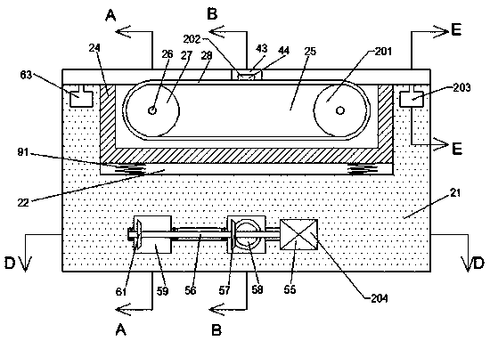
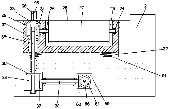
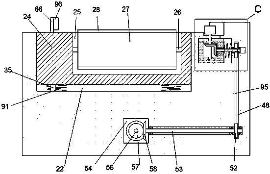
[0021] Combine below Figure 1-Figure 7 The present invention is described in detail, and for convenience of description, the orientations mentioned below are now stipulated as follows: figure 1 The up, down, left, right, front and back directions of the projection relationship itself are the same.

[0022] The present invention relates to an automatic plate edging machine, which is mainly used in the process of plate edging. The present invention will be further described below in conjunction with the accompanying drawings of the present invention:

[0023] An automatic plate edging machine according to the present invention includes a workbench 21, a travel sliding chamber 22 is arranged in the upper end surface of the workbench 21, and a lifting slider 24 is slid inside the travel slide chamber 22, and the Four traveling compression springs 91 are evenly distributed on the lower side of the lifting slider 24, and a traveling device 201 is arranged inside the lifting slider...


PUM


Abstract

The invention discloses an automatic plate edge-grinding machine. The automatic plate edge-grinding machine comprises a workbench, wherein a running slide cavity is formed in the upper end surface ofthe workbench; a lifting slide block is slidably arranged in the running slide cavity; four running compression springs are uniformly distributed and fixedly arranged at the lower side of the liftingslide block; a running device is arranged in the lifting slide block; and the running device is used for driving a plate needing to be subjected to edge-grinding to move to left and right on the upperend surface of the workbench. According to the automatic plate edge-grinding machine, the plate is driven to move and the edge of the plate is grinded through a grinding wheel at a fixed position andthe running device; through the action of grinding springs, closer contact between the plate and the grinding wheel, and a better grinding effect are achieved, the loss speed of the grinding wheel can be effectively reduced, and inconvenience brought due to frequent replacement for the grinding wheel is avoided; the position of the plate is limited through a fastening device, so that the grindingaccuracy is guaranteed, and the grinding quality is ensured; and the grinding working is automatically carried out, and manual intervention is not needed during the grinding working, so that higher working efficiency is achieved while the labor is saved.

Description

technical field [0001] The invention relates to the technical field of non-metal processing, in particular to an automatic plate edging machine. Background technique [0002] In the process of plate processing, it is necessary to perform grinding work on the periphery of the plate. The traditional edge grinding of the plate is generally done manually. While the labor intensity of the workers is high, the grinding efficiency is low. At the same time, due to the instability of the manual work, the edge is prone to incomplete grinding during grinding. However, the traditional board edge grinding devices are mostly hand-held devices, and the contact with the edge of the board is unstable. When moving, the force on the grinding wheel and the board will change frequently, resulting in excessive wear of the grinding wheel, and frequent replacement of the grinding wheel is required. Work efficiency decline. Contents of the invention [0003] technical problem: [0004] The tradi...

Claims


Application Information

Patent Timeline
Patent Type & Authority Applications(China)
IPC IPC(8): B24B9/00B24B41/06B24B47/12B24B47/20B24B47/22
CPCB24B9/002B24B41/06B24B47/12B24B47/20B24B47/22
Inventor 杨翠芳
Owner 宁波暮春自动化科技有限公司
Why Eureka
Try Eureka