
Pile pressing equipment

A pile-pressing equipment and pile-pressing technology, applied in sheet pile walls, buildings, foundation structure engineering, etc., can solve the problem that it is difficult to control the level and height of piles that have been driven, it is difficult to flexibly adapt to the guide device, and the adjacent piles are affected. Solve problems such as force sinking, achieve the effect of flexible and convenient horizontal turning, stable and reliable clamping and fixing, flexible and free expansion and contraction

Pending Publication Date: 2019-11-08
浙江万坚建设有限公司
View PDF0 Cites 6 Cited by
  • Summary
  • Abstract
  • Description
  • Claims
  • Application Information

AI Technical Summary

Problems solved by technology

Obviously, large piling equipment is still needed, especially the guide device still needs other hoisting equipment to be hoisted to the piles that have been planted, and there is no piling equipment itself, and because the piles are close to each other, it is easy to rub when the piles are planted As a result, the adjacent piles are forced to sink, so it is difficult to control the piles to be level and equal in height
Another more obvious disadvantage is that the guiding device is difficult to flexibly adapt to the needs of some sites such as the river bank edge horizontally to the continuous zigzag turning pile planting.
In addition, the existing pile planting equipment sometimes encounters hard soil or rocks and other ground conditions, making it impossible to plant piles, and additional large-scale drilling equipment is required, which is costly and time-consuming and seriously affects construction efficiency.

Method used


Image

  • Pile pressing equipment
  • Pile pressing equipment
  • Pile pressing equipment

Examples


Embodiment Construction

[0026]The specific embodiments of the present invention will be further described below in conjunction with the accompanying drawings. What needs to be declared here is that the descriptions of these specific implementations are used to help understand the present invention, but are not intended to limit the present invention. In addition, the technical features involved in the various specific embodiments of the present invention described below may be combined with each other as long as they do not constitute conflicts with each other.

[0027] Such as figure 1 , figure 2 , image 3 , Figure 4 , Figure 5 , Figure 6 , Figure 7 Shown is the first embodiment

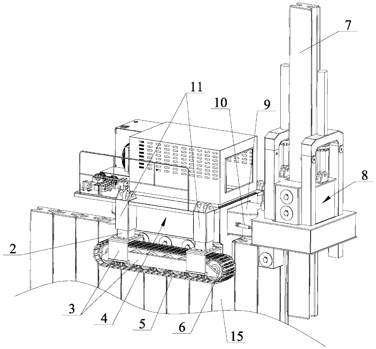
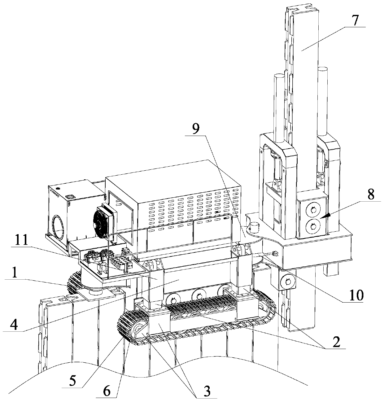
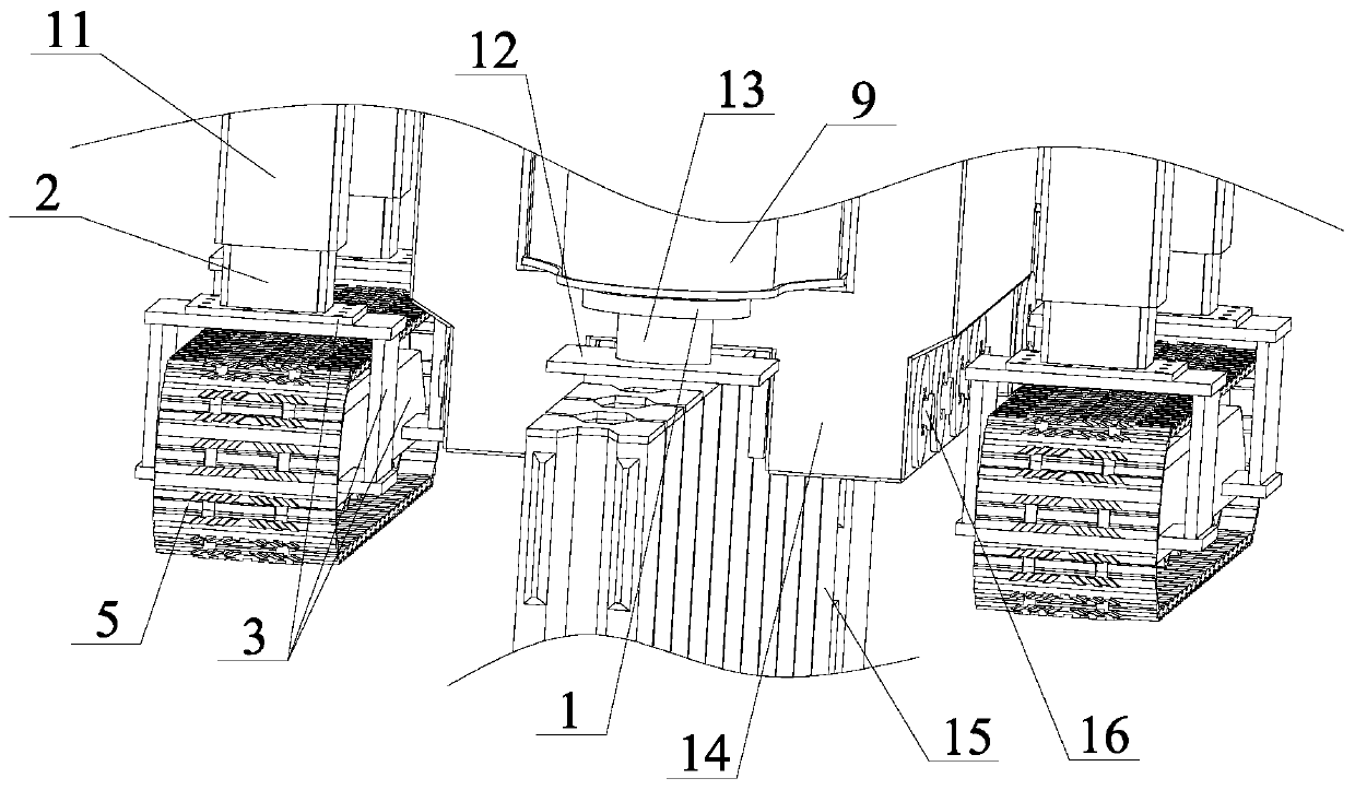
[0028] The pile pressing equipment of the present invention comprises a base 4, first clamping mechanisms on both sides fixed on both sides of the bottom of the base 4, a guide rail 9 slidingly fitted in the middle hole of the base, and arranged on the guide rail 9 and the base 4 for forward and backward movem...


PUM


Abstract

The invention discloses pile pressing equipment. The equipment comprises a base, first clamping mechanisms fixed to the two sides of the bottom of the base correspondingly, a first lifting oil cylinder fixed to the rear end of the base, a guide rail closed into a middle hole of the base in a sliding sleeving mode, and a horizontal moving oil cylinder which is arranged on the guide rail and the base and used for moving the base or the guide rail front and back. The equipment further comprises a pile pressing device arranged at the front end of the guide rail, and second clamping mechanisms arearranged on the two sides of the bottom of the pile pressing device. The equipment further comprises a crawler device and a lifting device which enable the base and the pile pressing device to be placed at the top of a planted pile. The front end of the guide rail is in the shape of an arc, the rear end of the pile pressing device is hinged to the front end of the guide rail, and turning oil cylinders used for enabling the pile pressing device to turn horizontally are arranged on the two sides of the front end of the guide rail; fixing blocks used for fixing lifting oil cylinders are hinged tothe rear end of the guide rail; and a rotary drilling machine is mounted on the pile pressing device. The pile pressing equipment can travel to the top end of the planted pile and is positioned or moved, and in addition, the pile pressing device can horizontally turn.

Description

technical field [0001] The invention relates to the technical field of foundation construction, in particular to pile pressing equipment. Background technique [0002] In the field of foundation construction technology, in many occasions, piles need to be closely attached to each other, pressed into the soil and extended along the length direction to form support piles or river cofferdams. The pressure piles or pile planting in the prior art generally initially plant a plurality of piles with a guide device, then set guide frames and other devices on the piles that have been planted, and then use a crane to place the piles to be implanted, such as rectangular piles, into the piles. Or hoist the I-shaped piles into the guide frame, and then use other piling equipment to plant piles in sequence. Obviously, large piling equipment is still needed, especially the guide device still needs other hoisting equipment to be hoisted to the piles that have been planted, and there is no ...

Claims


Application Information

Patent Timeline
IPC IPC(8): E02D7/20
CPCE02D7/20
Inventor 尚贤菊庄光明尚俏佳
Owner 浙江万坚建设有限公司
Learn More