Tiling robot and tiling method

A technology of robots and ceramic tiles, which is applied in the direction of architecture and building construction, can solve the problems of insignificant improvement of work efficiency, shortening of building decoration progress, and low overall work efficiency, so as to achieve high-efficiency actions, realize recycling, and improve The effect of utilization

Pending Publication Date: 2019-11-08
GUANGDONG BOZHILIN ROBOT CO LTD
View PDF7 Cites 22 Cited by
  • Summary
  • Abstract
  • Description
  • Claims
  • Application Information

AI Technical Summary

Problems solved by technology

Conventional tile laying workers work in groups of two, and can complete about 30 square meters of tile laying work in one day. The overall work efficiency is not high, which is not conducive to shortening the progress of building decoration
[0003] There are some auxiliary equipment for tile laying on the market, including tile grasping assistance and mortar pouring assistance, etc., but most of these existing auxiliary equipment are semi-automatic equipment, whi

Method used


Image

  • Tiling robot and tiling method
  • Tiling robot and tiling method
  • Tiling robot and tiling method

Examples


Embodiment 1

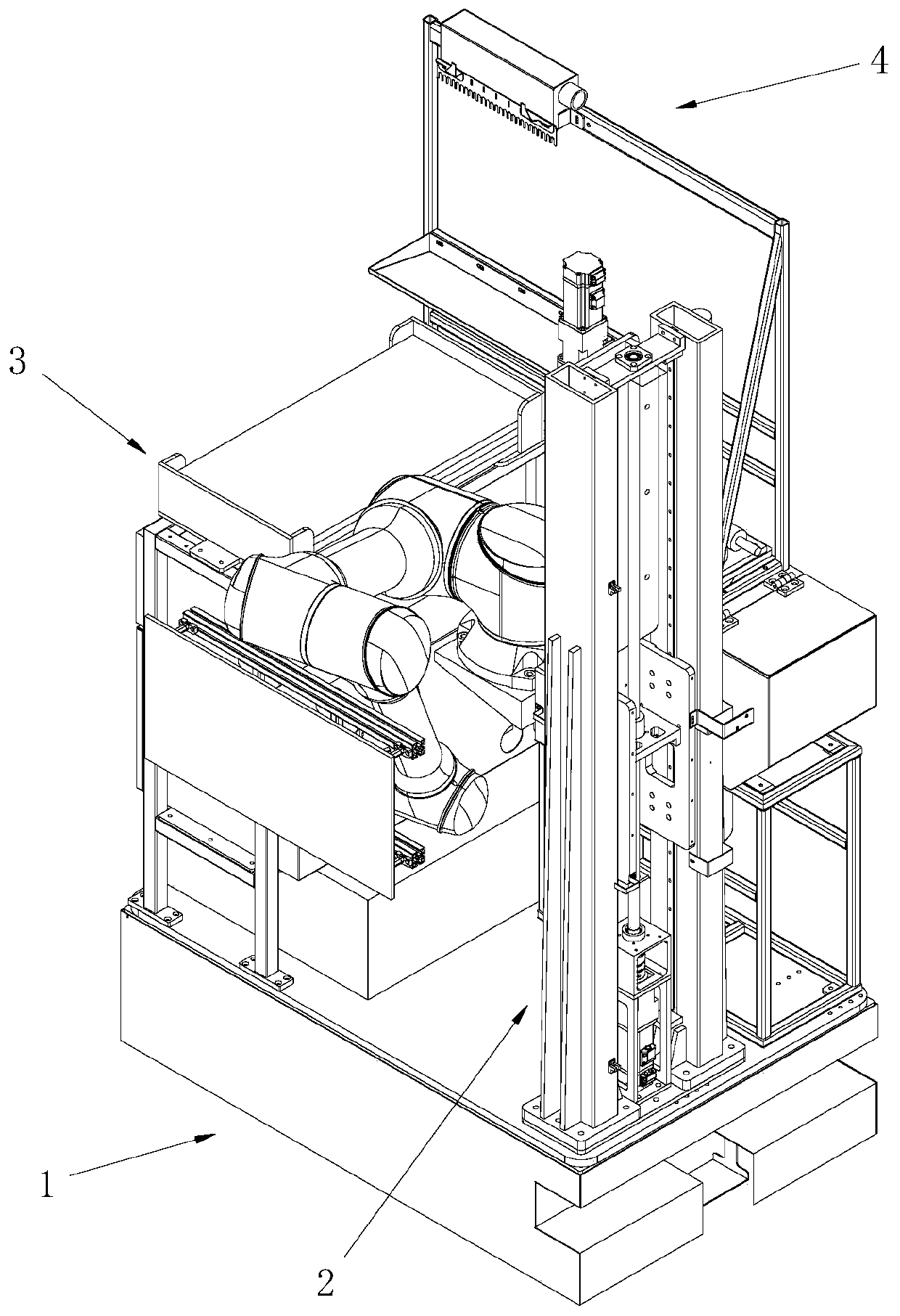
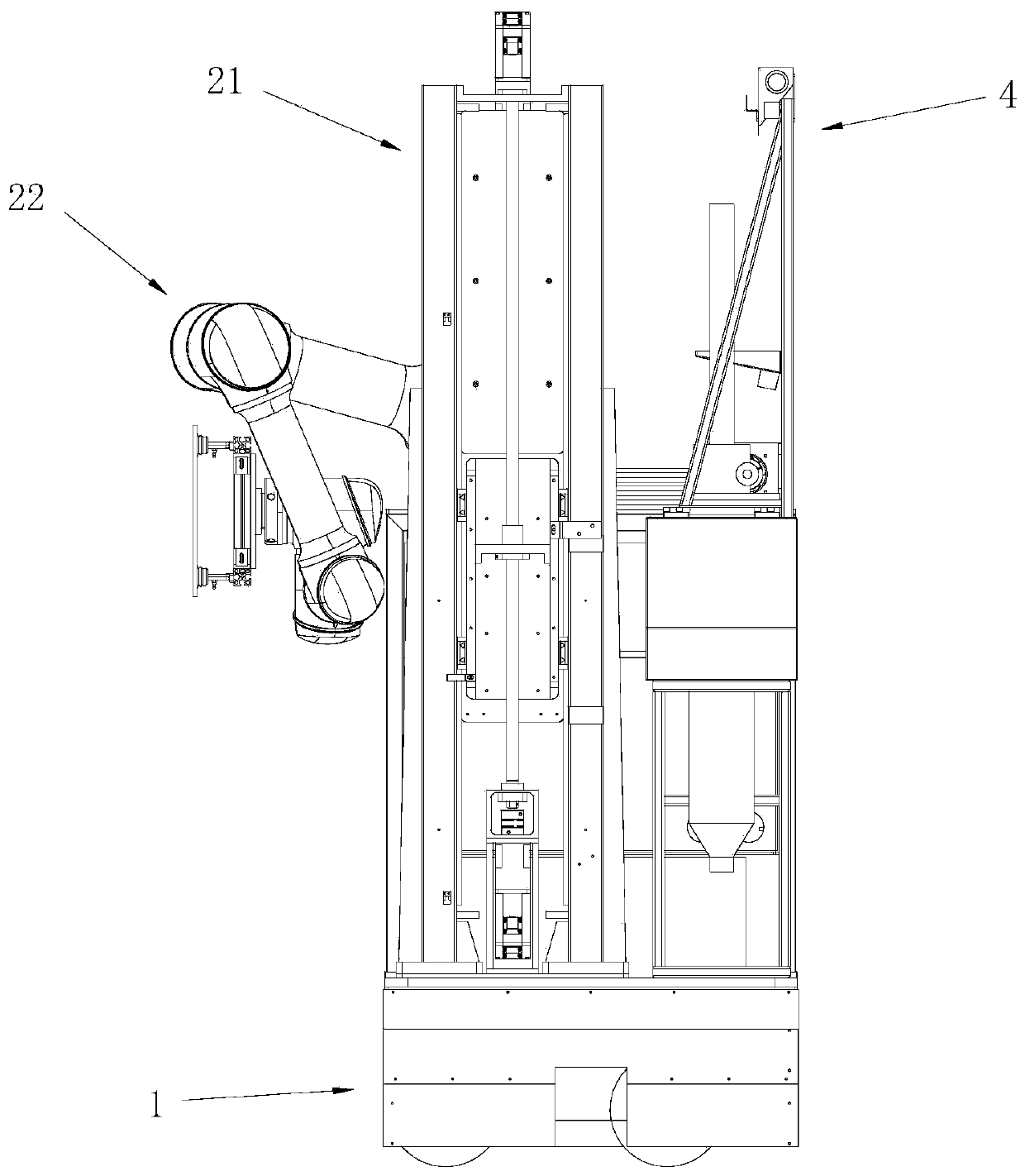
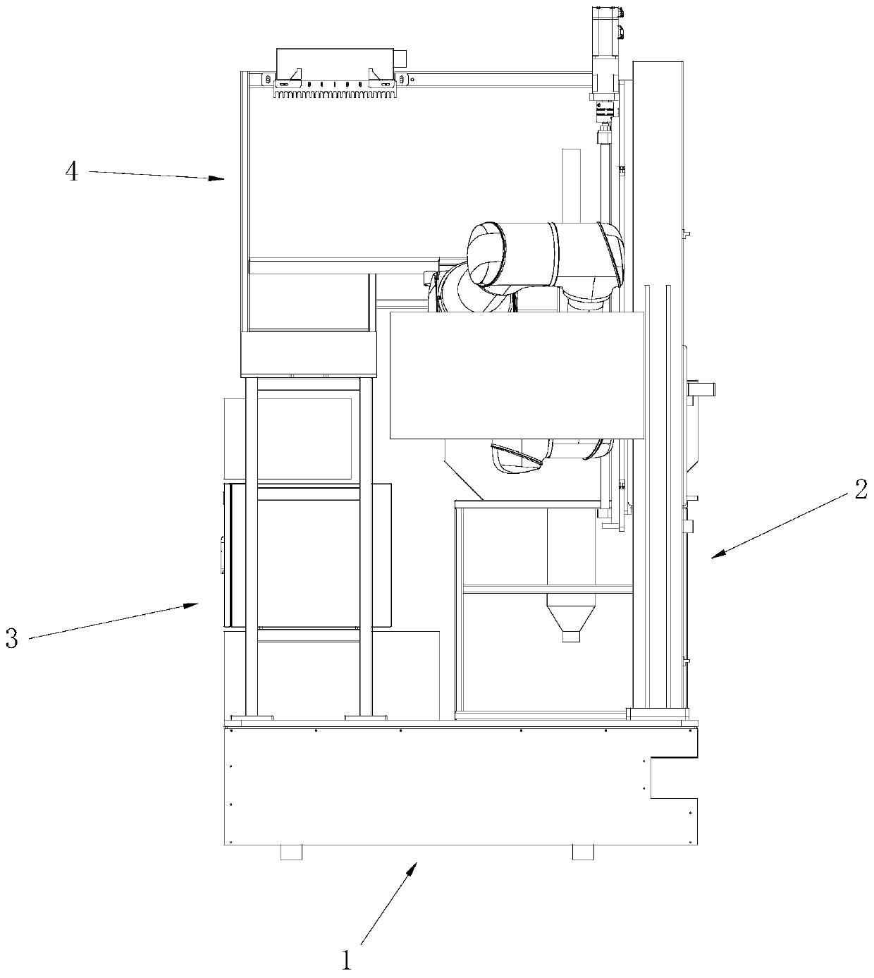
[0081] like Figure 1 to Figure 7 As shown, a tile laying robot includes a walking chassis 1 , a laying mechanism 2 , a tile placing frame 3 and a brushing mechanism 4 . The walking chassis 1 is configured to drive the overall movement of the robot. The first side 11 of the walking chassis 1 is a vacant area. During the tile laying process, the first side 11 of the walking chassis 1 is close to the building surface to be laid. The two sides 12 are adjacent to the first side 11 . The paving mechanism 2 is arranged on the second side 12 of the walking chassis 1, and is located at an end of the second side 12 close to the first side 11, and is configured to grab and transfer tiles to be laid. The tile placing frame 3 is mounted on the third side 13 of the walking chassis 1 and is configured to stack tiles to be laid. The brushing mechanism 4 is installed on the fourth side 14 of the walking chassis 1 and is configured to paint the tiles to be laid with adhesive.

[0082] The p...

Embodiment 2

[0095] The difference between this embodiment and Embodiment 1 is that the brushing mechanism further includes a linear slider, which is arranged on the upper cross bar of the upper support frame, and the brushing actuator is slidably connected with the upper support frame through the linear slider. The brushing actuator moves relative to the lifting device. During the painting process, the paving manipulator is stationary, and the brushing actuator moves linearly to achieve the coating of the adhesive.

Embodiment 3

[0097] A tile laying method, comprising the following steps:

[0098] S1. The walking chassis drives the tile placement rack, paving mechanism and brushing mechanism to move to the work station;

[0099] S5. Obtain the position information and inclination information of the walking chassis, position the paving mechanism through the position information, and perform positioning compensation adjustment on the paving mechanism through the inclination information;

[0100] S10, the paving mechanism grabs a tile from the tile placement rack;

[0101] S20. The paving mechanism transfers the tiles to the brushing mechanism, and the brushing mechanism paints the bonding material on the sticking surface of the tiles;

[0102] S30. The paving mechanism directs the painted tiles towards the building surface to be paved, and the paving mechanism pastes the tiles on the building surface to be paved;

[0103] S40. Judging whether the construction surface in the current work station has be...


PUM


Abstract

The invention belongs to the technical field of tiling, and discloses a tiling robot. The tiling robot comprises a walking chassis, a tiling mechanism, a tile holder and a painting mechanism, whereinthe first side of the walking chassis is a vacant area, the first side of the walking chassis is close to a to-be-tiled building surface in the tiling process, and the second side of the walking chassis is adjacent to the first side; the tiling mechanism is arranged on the second side of the walking chassis, and is located at the end, close to the first side, of the second side; the tile holder isinstalled on the third side of the walking chassis, and the painting mechanism is installed on the fourth side of the walking chassis. The invention also discloses a tiling method using the tiling robot. The tiling mechanism can transfer tiles in a short action stroke, so that the action of the tiling mechanism is more efficient; besides, painting of the tiles can be completed within the tiling robot, positioning of the tiling mechanism with the external environment is omitted, so that the structure of the robot is simplified, and the overall cost is reduced.

Description

technical field [0001] The invention relates to the technical field of tile laying, in particular to a tile laying robot and a laying method thereof. Background technique [0002] Building renovations generally require tiles to be laid on the walls of kitchens, bathrooms, and public areas. Due to the high technical precision of tile laying and the high requirements for the acceptance standard of wall tiles, at present, the work of laying tiles on the walls of large buildings is still mainly done by manual laying. Conventional tile laying workers work in teams of two, and can complete about 30 square meters of tile laying work in one day. The overall work efficiency is not high, which is not conducive to shortening the progress of building decoration. [0003] There are some auxiliary equipment for tile laying on the market, including tile grasping assistance and mortar pouring assistance, etc., but most of these existing auxiliary equipment are semi-automatic equipment, whi...

Claims


Application Information

Patent Timeline
IPC IPC(8): E04F21/18E04F21/22
CPCE04F21/1844E04F21/22
Inventor 张人才吴奇刘高俊何涛
Owner GUANGDONG BOZHILIN ROBOT CO LTD
Why Eureka
Try Eureka