Movable clamped anti-shock bracket and clamping sleeve combined part special tool

A technology of anti-seismic support and special tools, applied in the direction of pipes/pipe joints/fittings, pipe components, electrical components, etc., to achieve the effect of improving anti-seismic stability and improving stability

Pending Publication Date: 2019-11-08
HENAN AUSPIC TECH
View PDF1 Cites 0 Cited by
  • Summary
  • Abstract
  • Description
  • Claims
  • Application Information

AI Technical Summary

Problems solved by technology

[0005] Aiming at the defects and problems still existing in the existing anti-seismic support, the present invention provides an anti-seismic support capable of incr...

Method used


Image

  • Movable clamped anti-shock bracket and clamping sleeve combined part special tool
  • Movable clamped anti-shock bracket and clamping sleeve combined part special tool
  • Movable clamped anti-shock bracket and clamping sleeve combined part special tool

Examples


Embodiment 1

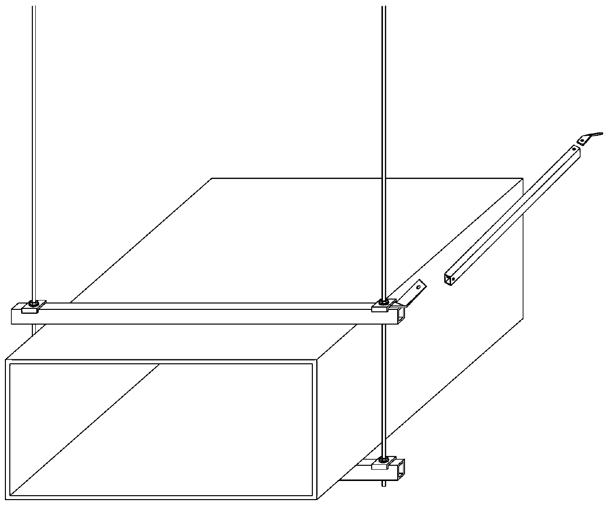
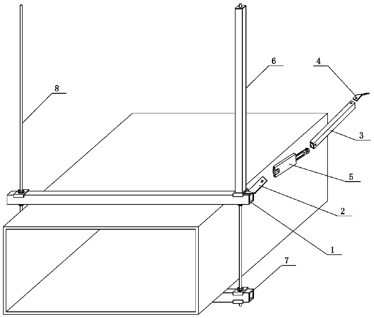
[0039] Embodiment 1: A movable clamping anti-seismic support such as figure 2 As shown, it includes a single support beam or connects auxiliary parts 7 etc. at the lower part of the support beam. There are suspenders 8 at both ends of the supporting beam 1. Usually, holes are drilled in the ceiling directly above the beam and expansion sleeves are installed. The suspenders are full-threaded screws. The upper end is threaded with the expansion sleeve, and the lower end is threaded with the end of the supporting beam. . The drawbars are scattered on the left and right sides or the outside of the end of the support beam, and usually there are multiple drawbars. Such as figure 2The lower end of the drawbar 3 is connected to the end of the support beam through the bottom corner connector 2, and the upper end of the drawbar is fixedly connected to the ceiling through the top corner connector 4 through the expansion wire.

[0040] compared to figure 1 Prior art connection mode,...

Embodiment 2

[0042] Embodiment 2: This embodiment improves the ferrule assembly on the basis of Embodiment 1. Specifically, a toothed rack 508 is formed on the outer side of the two fork levers of the card joint, such as Figure 6-Figure 8 As shown, setting the rack on the outside of the two-fork lever can utilize a jig or a special tool to press the rack to force it into the sleeve.

[0043] For example, using Figure 9-Figure 13 The special tool shown, the special tool includes an I-shaped bracket, a fixed side shaft is vertically connected between the two side wings of the I-shaped bracket, a rotating sleeve is set on the outside of the fixed side shaft, and a horizontal rotation shaft is vertically connected to the side of the rotation sleeve, and the horizontal rotation shaft Gears are set on the upper sleeve, and a drive plate is set on the horizontal shaft at the same time. The drive plate and the gear are fitted and fixed, and the drive plate is connected with a handle. A gear ho...

Embodiment 3

[0045] Embodiment 3: another kind of movable clamping anti-seismic support, embodiment 1 has given the current such as figure 2 The installation structure of the anti-seismic bracket is shown, but this embodiment is also suitable for adopting a prestressed structure with multiple rods repelling each other. For example, put figure 2 The suspender in the suspension rod should be a support rod hinged up and down, that is, the upper end is hinged with the upper connecting piece through the pin shaft, the upper connecting piece is fixed on the ceiling through the expansion wire, and the lower end is hinged with the lower connecting piece through the pin shaft, and the lower connecting piece is fixed on the support end of beam. Or at the same time, a jacket support tube is sleeved on the outside of the support rod. The left and right symmetrical positions and the outer positions of the support rods or the overcoat support tubes are respectively connected as follows: figure 2 E...


PUM


Abstract

The invention discloses a movable clamped anti-shock bracket. The movable clamped anti-shock bracket comprises a supporting cross beam, draw bars and corner adapting pieces. A clamping sleeve combinedpart is connected between each corner adapting piece and the corresponding draw bar and comprises a sleeve seat and a clamping head, wherein the sleeve seat is a flat pipe body, the two sidewalls ofan inner cavity of the sleeve seat are provided with inner helical teeth; the clamping head comprises two symmetric elastic rod jaws; the outer end of each rod jaw is provided with an outward expansion clamping head; and the expansion clamping heads are inserted into the sleeve seat and can be clamped to the inner helical teeth through expansion force. When combined for use, the special tool and the clamping sleeve combined part can providing supporting for multi-angle supporting and drawing. The clamping sleeve combined parts can be unidirectionally pushed in, operation is easy and convenient, and the manufacturing cost is low. The clamping heads of the clamping sleeve combined parts are inserted into the corresponding sleeve seats, so that tensile fore and jacking force serve as counter-acting force, and the anti-shock stability of the movable clamped anti-shock bracket is improved.

Description

technical field [0001] The invention belongs to the technical field of pipeline anti-seismic auxiliary supports, and in particular relates to an adjustable anti-seismic support that can be flexibly assembled and disassembled and can add prestress to each independent bar. Background technique [0002] Existing components such as cable ducts or air ducts used on the top of buildings are made by inserting expansion wire sleeves on the roof (ceiling) and connecting the expansion wires as hanging parts. The connection strength is very weak. When an earthquake occurs, the building will swing. , the pipes installed on the top of the building will also swing along with the cables and other components. This component swing will not be eliminated by itself, and the swing amplitude of the components will gradually increase with the swing of the building, and may even resonate with the swing of the building , Repeated high-intensity swing action will cause damage to the fixed parts of t...

Claims


Application Information

Patent Timeline
IPC IPC(8): F16L55/035H02G3/04
CPCF16L55/035H02G3/0462
Inventor 魏鲁双刘尚蔚魏群
Owner HENAN AUSPIC TECH
Why Eureka
Try Eureka