Multifunctional pipeline airtightness detection device

A detection device and pipeline gas technology, which is applied in the field of multifunctional pipeline air tightness detection devices, can solve the problems of difficult separation of rubber columns and pipe nozzles, high cost, and large volume, and achieve easy promotion, low manufacturing cost, and device structure simple effect

Pending Publication Date: 2019-11-08
合肥和瑞机械制造有限公司
View PDF0 Cites 1 Cited by
  • Summary
  • Abstract
  • Description
  • Claims
  • Application Information

AI Technical Summary

Problems solved by technology

[0004] The purpose of the present invention is to provide a multifunctional pipeline airtightness detection device, which overcomes the shortcomings of the prior art and solves the problems of large volume and high cost of the prior art pipeline airtightness detection device. The elastic piston device composed of a rubber column and a movable rubber plug is inserted into the rubber column during detection, and the pipeline is pumped through the retraction of the movable rubber plug. If the pipeline does not leak, the interior will be in a negative pressure state, so the rubber It is difficult to disengage the column and the nozzle, and it is easy to disengage if there is an air leak, so as to judge the airtightness of the pipeline. The device structure is simple, the manufacturing cost is low, and it is easy to promote. At the same time, there are air holes and elastic rubber blocks inside the movable rubber plug. When the movable rubber plug moves toward the mouth of the nozzle, there is air pressure to set the rubber block apart, and the air passes through the movable rubber plug. When the movable rubber plug retracts, the rubber block fits on the air hole, thereby sealing the movable rubber plug to play a role. pumping effect

Method used


Image

  • Multifunctional pipeline airtightness detection device
  • Multifunctional pipeline airtightness detection device
  • Multifunctional pipeline airtightness detection device

Examples


Embodiment Construction

[0018] The following will clearly and completely describe the technical solutions in the embodiments of the present invention with reference to the accompanying drawings in the embodiments of the present invention. Obviously, the described embodiments are only some, not all, embodiments of the present invention. Based on the embodiments of the present invention, all other embodiments obtained by persons of ordinary skill in the art without making creative efforts belong to the protection scope of the present invention.

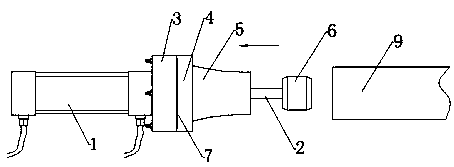
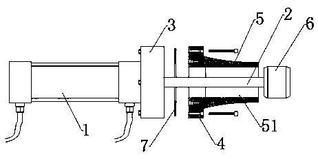
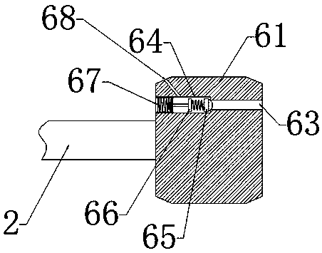
[0019] As shown in the figure, a multifunctional pipeline airtightness detection device according to the present invention includes a telescopic structure 1 and a pipeline to be detected 9, the front end of the telescopic structure is provided with a telescopic rod 2, and the front end of the telescopic structure is provided with a fixing plate 3. The surface of the fixed plate 3 is connected with a movable plate 4 by bolts. The movable plate 4 is a ring struct...


PUM


Abstract

The invention belongs to the technical field of pipeline processing gauges and particularly relates to a multifunctional pipeline airtightness detection device. The multifunctional pipeline airtightness detection device comprises a telescopic structure and a to-be-detected pipeline, wherein a telescopic pole is arranged at the front end of the telescopic structure; a fixed plate is arranged at thefront end of the telescopic structure; the surface of the fixed plate is connected with a movable plate through bolts; the movable plate is of a circular ring structure; a rubber column concentric with the circular ring structure is arranged on the circular ring structure; the outside diameter of the rubber column is gradually reduced along the extension direction of the telescopic structure; a round hole is formed in the middle of the rubber column; a movable rubber plug is arranged at a free end of the telescopic pole; the movable rubber plug is matched with the round hole to form a pistonstructure; and the diameter of one end, close to the movable plate, outside the rubber column is greater than that of an orifice of the to-be-detected pipeline and the diameter of the other end is smaller than that of the orifice of the to-be-detected pipeline. The shortcomings of the prior art are overcome and the multifunctional pipeline airtightness detection device is simple in structure, lowin manufacture cost and easy to popularize.

Description

technical field [0001] The invention belongs to the technical field of pipeline processing inspection tools, and in particular relates to a multifunctional pipeline airtightness detection device. Background technique [0002] Stainless steel pipe is a hollow long round steel material, which is widely used in petroleum, chemical, medical, food, light industry, mechanical instrumentation and other industrial pipelines and mechanical structural components. In addition, when the bending and torsional strength are the same, the weight is lighter, so it is also widely used in the manufacture of mechanical parts and engineering structures. It is also commonly used as furniture and kitchen utensils. [0003] Among them, the stainless steel pipe needs to be bent and welded during the processing process, so it cannot be completely guaranteed that the processed stainless steel pipe must be airtight, so it needs to be tested, but the existing detection device is large in size and high ...

Claims


Application Information

Patent Timeline
Patent Type & Authority Applications(China)
IPC IPC(8): G01M3/02
CPCG01M3/02
Inventor 陈欢迎杨文峰王银才
Owner 合肥和瑞机械制造有限公司
Why Eureka
Try Eureka