Antenna unit, antenna array and antenna

A technology of antenna unit and antenna array, which is applied in the direction of antenna array, separately energized antenna array, antenna, etc., can solve the problems of decreased radar detection ability and interference from the other party, and achieve the goal of improving detection ability, avoiding interference, and improving anti-interference ability Effect

Active Publication Date: 2019-11-08
XIAN TIANHE DEFENCE TECH
View PDF6 Cites 3 Cited by
  • Summary
  • Abstract
  • Description
  • Claims
  • Application Information

AI Technical Summary

Problems solved by technology

However, the traditional grid antenna adopts the method of feeding rectangular patches in series. In a complex environment, such as when two vehicles meet, t

Method used


Image

  • Antenna unit, antenna array and antenna
  • Antenna unit, antenna array and antenna
  • Antenna unit, antenna array and antenna

Examples


Example Embodiment

[0035] In order to make the purpose, technical solutions, and advantages of this application clearer, the following further describes the application in detail with reference to the accompanying drawings and embodiments. It should be understood that the specific embodiments described here are only used to explain the application, and not used to limit the application.

[0036] The antenna unit, antenna array, and antenna provided in the embodiments of this application can be applied to a 24GHz automotive collision avoidance radar. The technical solution of this application and how the technical solution of this application solves the above technical problems will be described in detail below with specific embodiments. The following specific embodiments can be combined with each other, and the same or similar concepts or processes may not be repeated in some embodiments. The embodiments of the present application will be described below in conjunction with the drawings.

[0037] fi...


PUM


Abstract

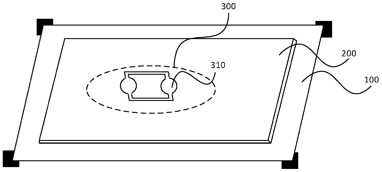
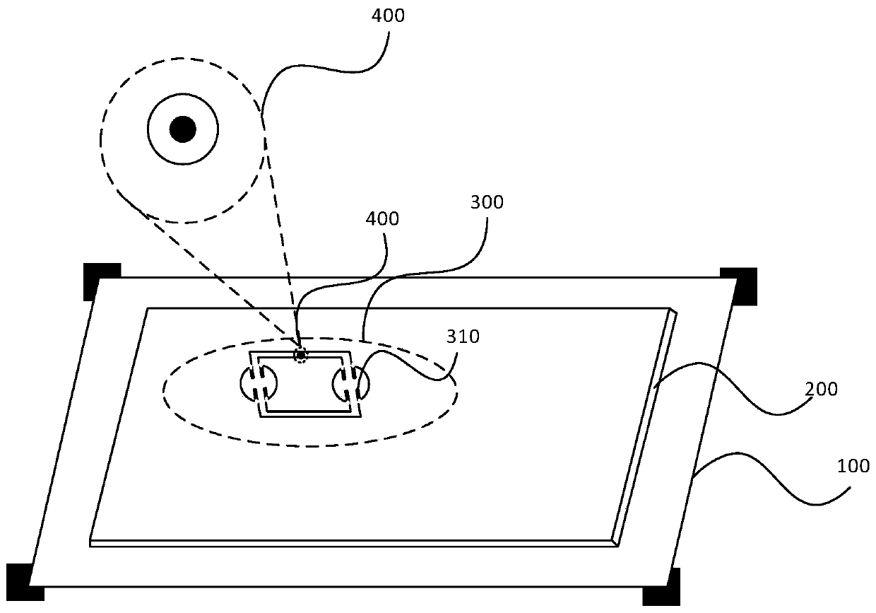
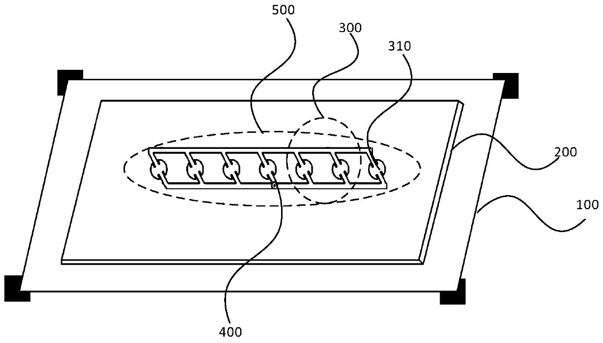
The application relates to an antenna unit, an antenna array and an antenna. The antenna unit includes a metal ground layer, a dielectric substrate and an antenna cell unit; the metal ground layer andthe antenna cell unit are respectively disposed on two opposite surfaces of the dielectric substrate; the antenna cell unit has a parallelogram shape, and the antenna cell unit is disposed in a 45-degree polarization manner; the long side and the short side of the antenna cell unit are two adjacent sides; and at least one short side of the antenna cell unit is provided with a radiating element. The antenna can reduce interference and can improve the detection performance of the radar when the vehicle is in use.

Description

technical field [0001] The present application relates to the technical field of communications, and in particular to an antenna unit, an antenna array and an antenna. Background technique [0002] With the development of communication technology, people have higher and higher requirements for the communication capabilities of communication equipment such as radar. As a tool for transmitting and receiving electromagnetic waves, the performance of the antenna plays a vital role in the communication capability of the communication equipment. [0003] Taking the millimeter-wave vehicle-mounted anti-collision radar as an example, traditional grid antenna arrays or rectangular series-fed array antennas are usually used to transmit and receive signals. However, the traditional grid antenna adopts the method of feeding rectangular patches in series. In a complex environment, such as when two vehicles meet, the simultaneous transmission and reception of signals between two vehicles...

Claims


Application Information

Patent Timeline
IPC IPC(8): H01Q1/32H01Q1/38H01Q1/48H01Q1/50H01Q1/52H01Q15/24H01Q21/00H01Q21/06H01Q21/08
CPCH01Q1/3233H01Q1/38H01Q1/48H01Q1/50H01Q1/521H01Q15/24H01Q21/0006H01Q21/061H01Q21/08
Inventor 李向坤徐俊珺李红芳
Owner XIAN TIANHE DEFENCE TECH
Why Eureka
Try Eureka