
Noise reduction method and system for a pulse array signal

An array signal and pulse technology, applied in the field of signal processing, can solve the problems of low time domain resolution, large video data redundancy, unable to reflect the dynamic changes of the scene, etc., and achieve the effect of good noise reduction and high efficiency.

Active Publication Date: 2020-08-25
SPIKE VISION (BEIJING) TECHNOLOGY CO LTD
View PDF6 Cites 0 Cited by
  • Summary
  • Abstract
  • Description
  • Claims
  • Application Information

AI Technical Summary

Problems solved by technology

This kind of sampling based on a fixed frame rate cannot reflect the dynamic changes of the scene, and it is easy to oversample or undersample the current scene, resulting in large video data redundancy, low temporal resolution, and easy blurring under high-speed motion.

Method used


Image

  • Noise reduction method and system for a pulse array signal
  • Noise reduction method and system for a pulse array signal
  • Noise reduction method and system for a pulse array signal

Examples


Embodiment Construction

[0041] In order to make the object, technical solution and advantages of the present invention clearer, the present invention will be further described below in conjunction with the accompanying drawings and specific embodiments. It should be understood that the specific embodiments described here are only used to explain the present invention, not to limit the present invention. Based on the embodiments of the present invention, all other embodiments obtained by persons of ordinary skill in the art without making creative efforts belong to the protection scope of the present invention.

[0042]Those skilled in the art can understand that, unless otherwise defined, all terms (including technical terms and scientific terms) used herein have the same meaning as commonly understood by those of ordinary skill in the art to which this invention belongs. It should also be understood that terms, such as those defined in commonly used dictionaries, should be understood to have meaning...


PUM


Abstract

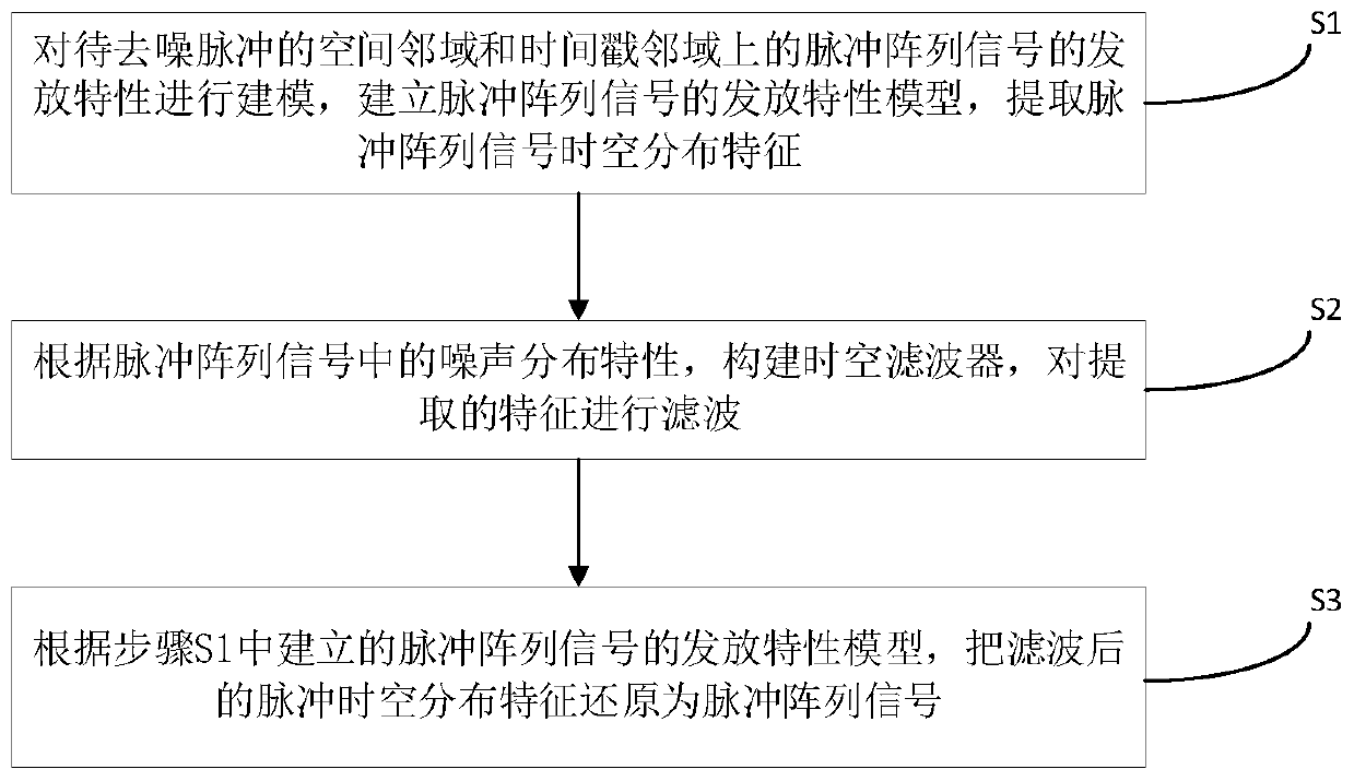
The invention discloses a pulse array signal noise reduction method, which comprises the following steps of: modeling distribution characteristics of pulse array signals in a spatial neighborhood anda timestamp neighborhood of a pulse to be denoised, establishing a distribution characteristic model of the pulse array signals, and extracting space-time distribution characteristics of the pulse array signals; constructing a space-time filter according to noise distribution characteristics in the pulse array signal, and filtering the extracted characteristics; and restoring the filtered pulse space-time distribution characteristics into pulse array signals according to the distribution characteristic model. The space-time distribution characteristics of the noise in the pulse array signal are fully considered. The modeling is carried out on the transitivity of the noise in the time domain and the randomness of the noise in the space domain. The physical significance represented by the pulse is combined. The space-time filter is constructed to carry out efficient denoising on the pulse signal. The efficiency is high, and the denoising effect is good.

Description

technical field [0001] The invention relates to the technical field of signal processing, in particular to a noise reduction method and system for pulse array signals. Background technique [0002] Traditional vision sensors usually take frames as units, and perform complete sampling of the scene according to a preset fixed frequency. This kind of sampling based on a fixed frame rate cannot reflect the dynamic changes of the scene, and it is easy to oversample or undersample the current scene, resulting in large video data redundancy, low temporal resolution, and easy blurring under high-speed motion. Inspired by the visual sampling mechanism of the biological retina, new cameras that collect pulse array signals have entered people's field of vision, including sensors that emit pulse signals based on changes in light intensity, such as Dynamic Vision Sensor (DVS), image sensors based on asynchronous time (Asynchronous Time-based image Sensor, ATIS), dynamic active pixel vis...

Claims


Application Information

Patent Timeline
Patent Type & Authority Patents(China)
IPC IPC(8): H04N5/213
CPCH04N5/213
Inventor 田永鸿朱林李家宁付溢华董思维黄铁军
Owner SPIKE VISION (BEIJING) TECHNOLOGY CO LTD
Learn More