High-efficiency energy-saving particle production device and using method thereof

A high-efficiency, energy-saving, production device technology, applied in the direction of mold extrusion granulation, drying gas arrangement, dryer, etc., can solve the problems of reducing production efficiency, wear of ring die and pressure roller, and increasing production cost, achieving convenience and speed The effect of collecting, slowing down mutual wear and prolonging service life

Inactive Publication Date: 2019-11-12
安徽群升建筑工程有限公司
View PDF1 Cites 5 Cited by
  • Summary
  • Abstract
  • Description
  • Claims
  • Application Information

AI Technical Summary

Problems solved by technology

[0004] The purpose of the present invention is to provide a high-efficiency and energy-saving particle production device and its use method. In order to overcome the high temperature generated by the high rotation of the existing pressure rollers in the ring die, in addition to softening the raw materials, it will cause the ring die to heat up, and the long time The continuous operation of the ring die and the pressure roller at high temperature will cause the wear between the ring die and the pressure roller to increase, resulting in serious wear between the ring die and the pressure roller. The service life of the roller; at the same time, the existing raw material drying process uses a separate drying device to dry the raw material, which wastes energy and increases production costs; at the same time, the extruded particles are pushed to the storage funnel and piled up in large quantities. It is necessary to deal with the particles in the storage funnel in time, which affects the production and reduces the technical problem of production efficiency

Method used


Image

  • High-efficiency energy-saving particle production device and using method thereof
  • High-efficiency energy-saving particle production device and using method thereof
  • High-efficiency energy-saving particle production device and using method thereof

Examples


Embodiment Construction

[0036] The technical solutions of the present invention will be clearly and completely described below in conjunction with the embodiments. Apparently, the described embodiments are only some of the embodiments of the present invention, not all of them. Based on the embodiments of the present invention, all other embodiments obtained by persons of ordinary skill in the art without creative efforts fall within the protection scope of the present invention.

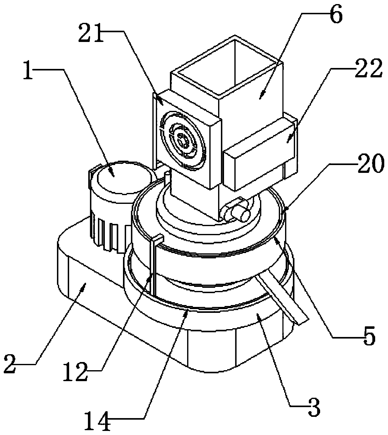
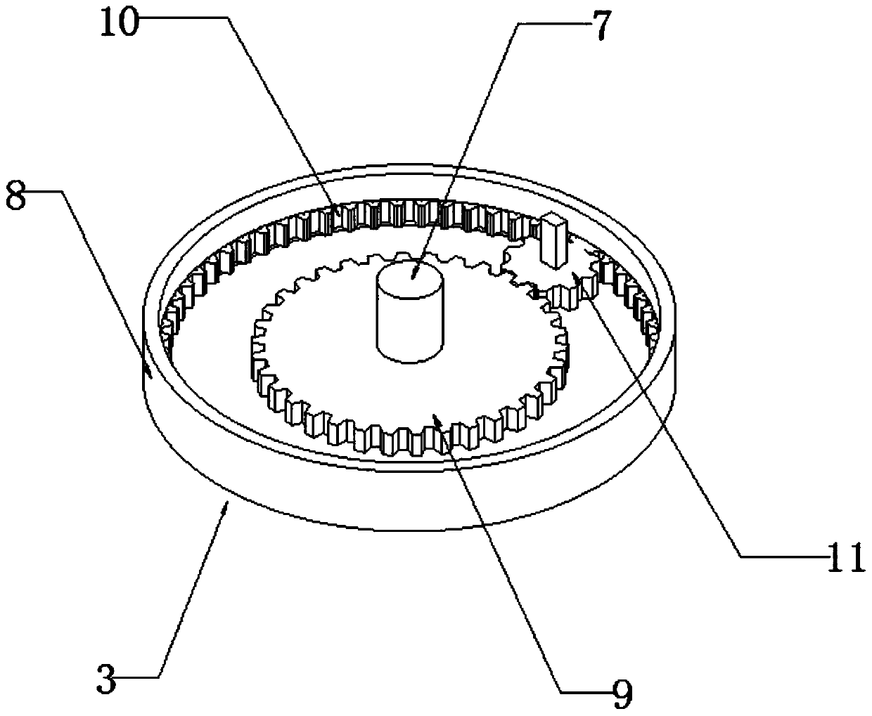
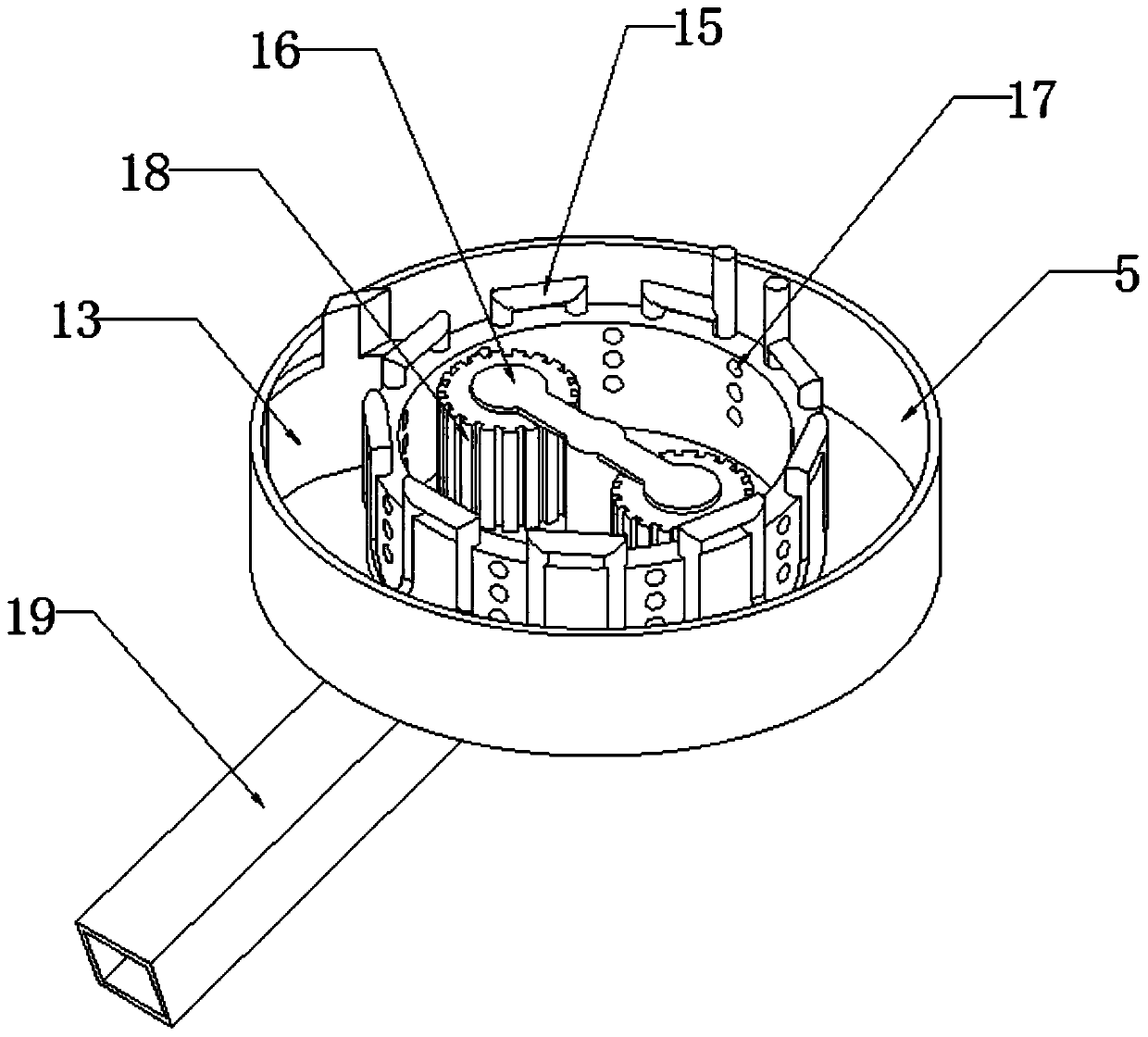
[0037] see Figure 1-5As shown, a high-efficiency and energy-saving particle production device includes a first servo motor 1, a reducer 2, a planetary mechanism 3, a ring die 4, a storage cover 5 and a storage funnel 6, and the upper side of the reducer 2 is connected to the first The output end of the servo motor 1 is connected, the planetary mechanism 3 is installed on the other side above the reducer 2, the ring die 4 is installed above the planetary mechanism 3, the material storage cover 5 is installed on the outer si...


PUM


Abstract

The invention discloses a high-efficiency energy-saving particle production device, comprising a first servo motor, a speed reducer, a planetary mechanism, a ring mold, a material storage cover and amaterial storage hopper. One side on the speed reducer is connected to an output end of the first servo motor, and the other side on the speed reducer is provided with the planetary mechanism. The ring mold is mounted on the planetary mechanism. The material storage cover is mounted outside the ring mold. The material storage hopper is on the material storage cover. An output end at the other sideof the speed reducer is provided with a transmission rotation shaft. The top end of the transmission rotation shaft penetrates the centers of the planetary mechanism and the ring mold in order. Material collection is achieved through transmission of the planetary mechanism through rotation the device itself during work. Heat in the device is effectively collected to avoid influences of high temperature on the ring mold and a pressure roller, and the collected heat is reutilized; humidity of a raw material is adjusted, thus greatly saving loss of resources and increasing the production efficiency.

Description

technical field [0001] The invention relates to the field of electromechanical equipment, in particular to a high-efficiency and energy-saving particle production device and a use method thereof. Background technique [0002] The granulator with the patent publication number (CN 205672876) cannot dissipate heat from the high-temperature parts in the production process, which affects the long-term operation of the device. At the same time, the granules produced cannot be collected in time and are easy to accumulate in the storage funnel. [0003] The high temperature generated by the high rotation of the existing pressure roller in the ring die not only softens the raw material, but also causes the temperature of the ring die to rise, and the continuous operation of the ring die and the pressure roller at high temperature for a long time causes the thermal expansion of the ring die and the pressure roller to increase the wear between the ring die and the pressure roller , res...

Claims


Application Information

Patent Timeline
Patent Type & Authority Applications(China)
IPC IPC(8): B01J2/22B02C4/02F26B21/00
CPCB01J2/22B02C4/02F26B21/001F26B21/004
Inventor 代群鲁荣范红代琴
Owner 安徽群升建筑工程有限公司
Why Eureka
Try Eureka