A method for automatic orientation optimization of dental crown models based on 3D printing

A dental crown model and 3D printing technology, which can be used in manufacturing auxiliary devices, other household appliances, processing data acquisition/processing, etc., can solve problems such as poor placement effects, and achieve saving precious time, time efficiency, and high quality Effect

Active Publication Date: 2021-05-04
上海漫格科技有限公司
View PDF7 Cites 0 Cited by
  • Summary
  • Abstract
  • Description
  • Claims
  • Application Information

AI Technical Summary

Problems solved by technology

[0007] The technical problem to be solved by the present invention is to overcome the disadvantages of the prior art, provide a method for automatically optimizing the direction of the crown model based on 3D printing, solve the problem of placing the crown model before 3D printing, and make the printing time more efficient. and print quality results are better; for staff who use other 3D printing software, it can reduce their time cost of learning complex software, and at the same time avoid the problem of poor placement caused by other software; for manual operation, adjust For the staff who place the crown model, it greatly reduces their operating time and improves their manufacturing efficiency

Method used


Image

  • A method for automatic orientation optimization of dental crown models based on 3D printing
  • A method for automatic orientation optimization of dental crown models based on 3D printing
  • A method for automatic orientation optimization of dental crown models based on 3D printing

Examples


Embodiment 1

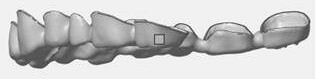
[0038] Model 1, a C-shaped crown with 14 crowns. combine Figure 1-Figure 4 ,according to figure 1 with image 3 The front views of model 1 before and after the two optimization directions show that the Z height of the crown model can be reduced to the minimum by the method of this paper.

[0039] according to figure 2 with Figure 4 The top view of model 1 before and after the two optimization directions shows that the opening height of the crown model can be made upward by the method in this paper.

[0040] Combining the above two points, the validity and accuracy of the method in this paper are verified.

Embodiment 2

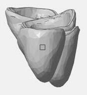
[0042] Model 2: A linear crown with 4 crowns. combine Figure 5-Figure 8 ,according to Figure 5 with Figure 7 The two front views of model 2 before and after the optimization direction show that the Z height of the crown model can be reduced to the minimum through the method of this paper.

[0043] according to Image 6 with Figure 8 The two top views of the model 2 before and after the optimization direction show that the method of this paper can make the opening height of the crown model face upward.

[0044] Combining the above two points, the validity and accuracy of the method in this paper are verified.

Embodiment 3

[0046] Model 3: A single crown with 1 crown model. combine Figure 9-Figure 12 ,according to Figure 9 with Figure 11 The front view of the model three before and after the two optimization directions shows that the Z height of the crown model can be reduced to the minimum through the method of this paper.

[0047] according to Figure 10 with Figure 12 The top view of model 3 before and after the two optimization directions shows that the opening height of the crown model can be made to face upward through the method of this paper.

[0048] Combining the above two points, the validity and accuracy of the method in this paper are verified.


PUM


Abstract

The invention relates to an automatic direction optimization method for a crown model based on three-dimensional printing, which solves the problem of placing the crown model before three-dimensional printing, so that the printing time efficiency and printing quality results are better; for the use of other three-dimensional printing For the software staff, it can reduce their time cost of learning complex software, and at the same time avoid the problem of poor placement effect caused by other software; for the staff who manually adjust the placement direction of the crown model, a lot Reduce their operating time and improve their manufacturing efficiency.

Description

technical field [0001] The invention relates to the technical field of three-dimensional printing, in particular to an automatic direction optimization method for a crown model based on three-dimensional printing. Background technique [0002] The following problems exist in the existing 3D printing technology: [0003] 1. The model direction optimization in the existing 3D printing software is to allow the user to set or select certain parameters, such as the Z-axis height of the model, support area, support volume, XY projected area, etc. If these parameters are set properly, the crown model It can be optimized to a very suitable direction and is suitable for 3D printing. However, this operation requires a lot of learning costs. It is very impractical and inefficient for doctors or related staff who actually operate 3D printing of dental crown models. . [0004] 2. Some 3D printing software direction optimization, simple operation, no need for users to input various para...

Claims


Application Information

Patent Timeline
Patent Type & Authority Patents(China)
IPC IPC(8): B29C64/386B33Y50/00
CPCB29L2031/753B33Y50/00B29C64/386
Inventor 王松张朝鑫任泉珲郁萌安峰
Owner 上海漫格科技有限公司
Why Eureka
Try Eureka