Combined installation protective equipment for single silicon thermal field crucible and using method of combined installation protective equipment

A protective equipment and a combined technology, which is applied in the field of combined installation protective equipment for single-product silicon thermal field crucibles, can solve the problems of inconvenient loading and unloading of protective equipment, failure to achieve thermal field crucible protection, and increased labor costs, etc., to achieve Reduce labor installation costs, avoid hot field crucible damage, and prolong service life

Pending Publication Date: 2019-11-12
DATONG XINCHENG NEW MATERIAL CO LTD
View PDF15 Cites 1 Cited by
  • Summary
  • Abstract
  • Description
  • Claims
  • Application Information

AI Technical Summary

Problems solved by technology

[0003] When the current installation protection equipment protects the hot field crucible that needs to be transported, many of them are placed in a cabinet, and the two sides are clamped and fixed by two clamping blocks. However, this protection method , under the extrusion of external force, it is easy to cause deformation or damage of the hot field crucible, and the purpose of comprehensive protection of the hot field crucible cannot be achieved. Moreover, the existing installation and protection equipment is inconvenient to load and unload, which increases the labor cost. Therefore, we propose a single-product silicon thermal field crucible combined installation protection equipment and its use method to solve the above problems

Method used


Image

  • Combined installation protective equipment for single silicon thermal field crucible and using method of combined installation protective equipment
  • Combined installation protective equipment for single silicon thermal field crucible and using method of combined installation protective equipment
  • Combined installation protective equipment for single silicon thermal field crucible and using method of combined installation protective equipment

Examples


Embodiment Construction

[0033] The technical solutions in the embodiments of the present invention will be clearly and completely described below in conjunction with the accompanying drawings in the embodiments of the present invention. Obviously, the described embodiments are only a part of the embodiments of the present invention, rather than all the embodiments.

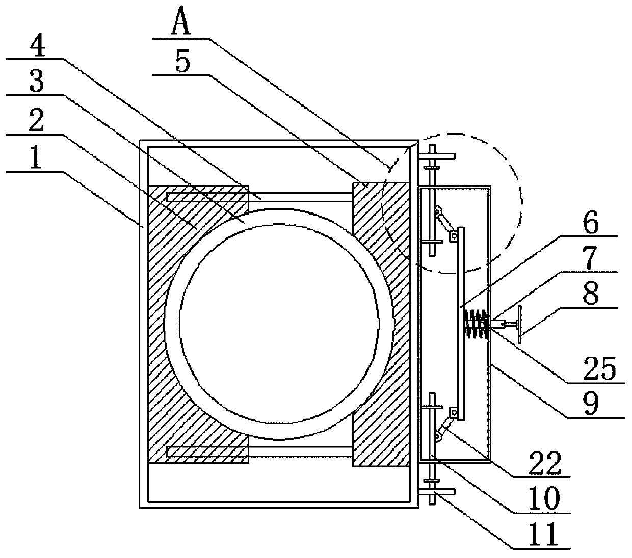
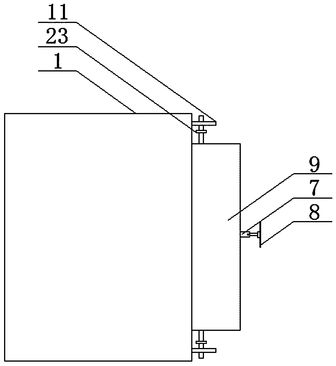
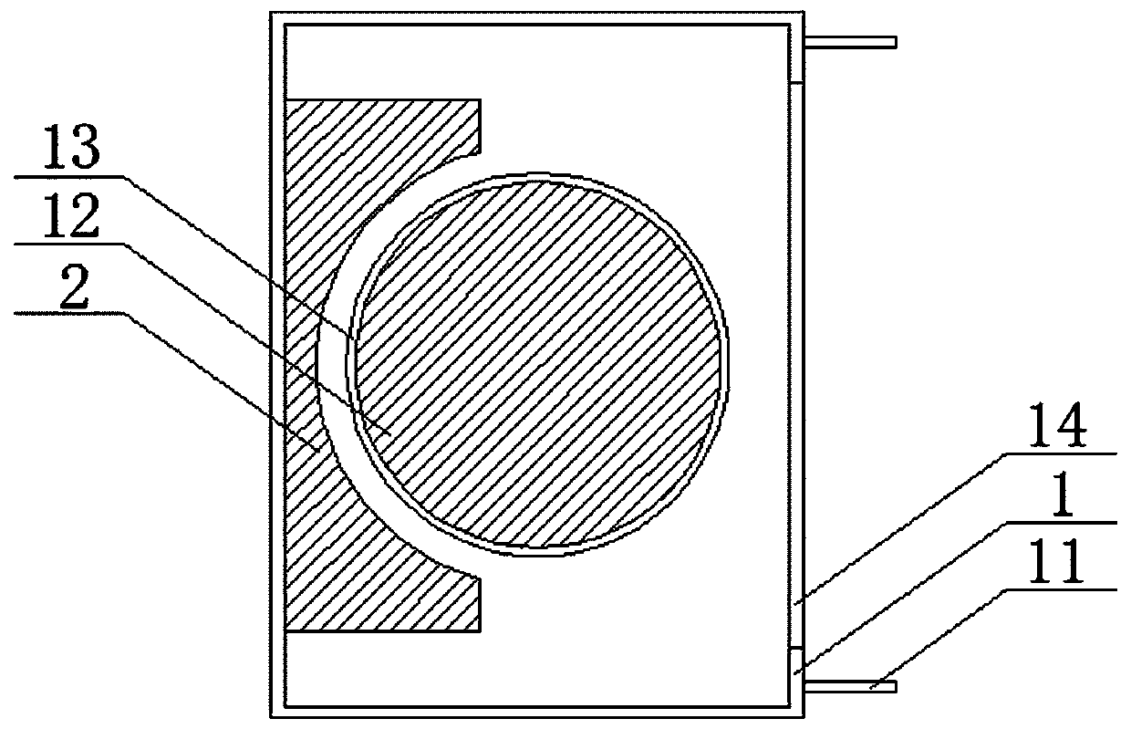
[0034] Reference Figure 1-8 , A combined installation and protection equipment for a single-product silicon hot field crucible, including a cabinet body 1, the crucible body 3 is placed in the cabinet body 1, the cabinet body 1 is provided with a cavity, and the bottom of the cavity is provided with a placing groove 13. A rubber pad 12 is provided at the bottom of the placement groove 13 to serve as a buffer and protection. A first opening 14 is provided on one side wall of the cavity, and two limit plates are fixed on one side wall of the cabinet 1 11, and two limiting plates 11 are located on both sides of the first opening 14, the two l...


PUM


Abstract

The invention discloses combined installation protective equipment for a single silicon thermal field crucible. The equipment comprises a cabinet; a cavity is disposed in the cabinet; a placement groove is formed in the bottom in the cavity; a rubber pad is disposed at the bottom in the placement groove; a first opening is formed in the side wall of one end of the cavity; two limiting plates are fixed to the side wall of one end of the cabinet; the two limiting plates are located on the two sides of the first opening; the two limiting plates are each provided with a second opening; and a second arc-shaped clamping block penetrates through the first opening. The invention further provides a using method of the combined installation protective equipment for the single silicon thermal field crucible. The thermal field crucible which is during transportation is comprehensively protected, the stability of the thermal field crucible is improved, the situation that the thermal field crucibleis damaged due to squeezing of external pressure or jolting during transportation is avoided, the service life of the thermal field crucible is prolonged, meanwhile the thermal field crucible is installed conveniently and fast, and the manual installation cost is reduced.

Description

Technical field [0001] The invention relates to the technical field of single-product silicon thermal field crucibles, in particular to a combined installation protection device for single-product silicon thermal field crucibles and a method of use thereof. Background technique [0002] Crucible is an important part of chemical instruments. It is a vessel for melting and refining liquid metal and heating and reacting between solid and liquid. It is the basis for ensuring the smooth progress of chemical reactions. Hot field crucibles are also a kind of crucible, and hot field crucibles are in production. After completion, it needs to be transported to a suitable place. When transporting, it needs to be protected by installing protective equipment. [0003] When the current installation protection equipment protects the hot crucible that needs to be transported, most of it is placed in a cabinet and fixed on both sides by two clamping blocks. However, this protection method Under th...

Claims


Application Information

Patent Timeline
Patent Type & Authority Applications(China)
IPC IPC(8): B65D25/02B65D25/10B65D25/38B65D81/05B65D85/68
CPCB65D25/02B65D25/10B65D25/38B65D81/05B65D85/68B65D2585/68
Inventor 马怡军
Owner DATONG XINCHENG NEW MATERIAL CO LTD
Why Eureka
Try Eureka