
Cantilever force-bearing frame and mounting method thereof

A load-bearing frame and overhanging technology, applied in the field of load-bearing frames, can solve problems such as consuming a lot of time and energy, and achieve the effects of reducing possibilities, increasing installation stability, and reducing labor burden

Active Publication Date: 2019-11-12
江苏溧阳建设集团有限公司
View PDF8 Cites 4 Cited by
  • Summary
  • Abstract
  • Description
  • Claims
  • Application Information

AI Technical Summary

Problems solved by technology

[0004] When installing the load-bearing frame in the prior art, since the first fixed rod is connected to the first horizontal steel pipe by welding, the second fixed rod is also connected to the vertical rod and the first horizontal steel pipe by welding. For scaffolding, multiple load-bearing frames need to be built. At this time, workers need to spend a lot of time and energy on welding, which needs to be improved

Method used


Image

  • Cantilever force-bearing frame and mounting method thereof
  • Cantilever force-bearing frame and mounting method thereof
  • Cantilever force-bearing frame and mounting method thereof

Examples


Embodiment 1

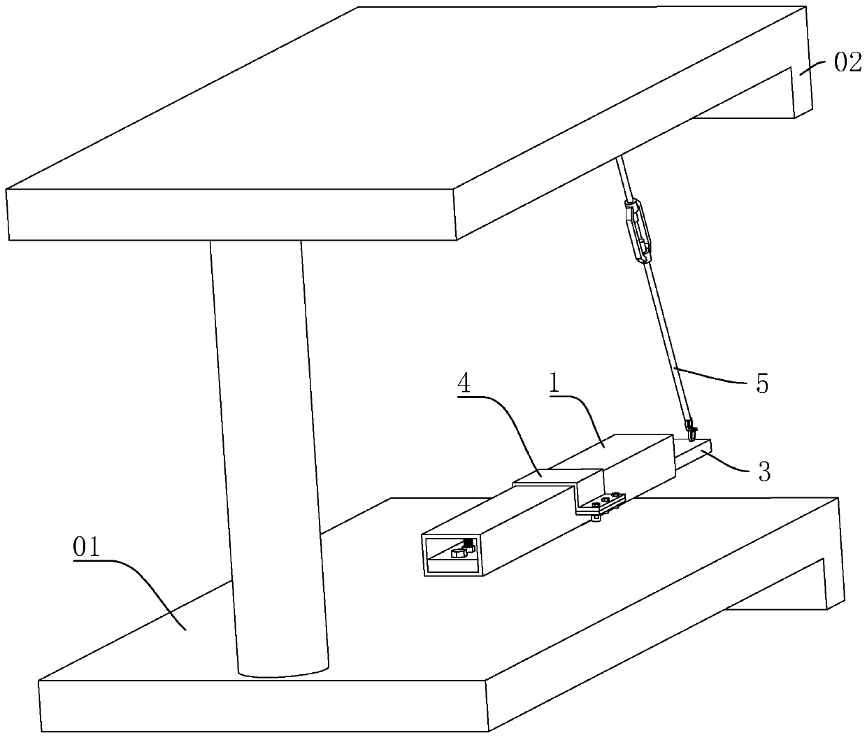
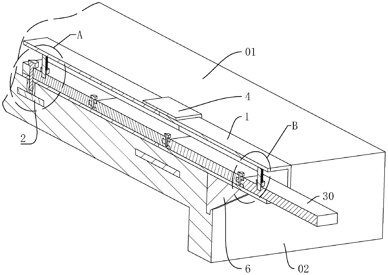
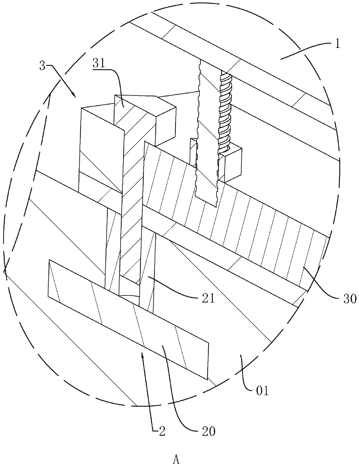
[0046] refer to figure 1 and figure 2 , a cantilever bearing frame, which includes a square pipe 1, a built-in part 2 arranged in the floor 01, a fixing part 3 inserted into the cavity of the square pipe 1 and connected with the built-in part 2, arranged in the floor 01 The limiting part 4 at the edge and used to fix the square pipe 1 and the hanging part 5 arranged on the wall 02 , the hanging part 5 is used to connect the end of the square pipe 1 away from the fixing part 3 .

[0047] refer to figure 1 and figure 2 , on the wall 02 and under the square tube 1, a reinforcing rib plate 6 is pre-embedded, and the top wall of the reinforcing rib plate 6 is in contact with the bottom wall of the square tube 1; the installation stability of the square tube 1 on the floor 01 is increased; When installing the load-bearing frame, insert the fixing part 3 into the cavity of the square tube 1, connect the embedded part 2 with the square tube 1, lift the square tube 1 with the susp...

Embodiment 2

[0058] A method for installing a cantilever bearing frame, specifically as follows:

[0059] (1) Pre-embed the pre-embedded plate, connecting sleeve, limit plate, connecting plate and limit column in the floor, and pre-embed the reinforcing rib plate and connecting screw in the wall;

[0060] (2) Put the square pipe on the floor, one part of the square pipe is installed on the floor, and the other part extends out of the floor, and the rib plate is pressed against the bottom wall of the square pipe to increase the installation stability of the square pipe on the floor; according to The length of the square tube, drill holes on the fixed block and the clamping block, insert the clamping block of the fixed block into the groove, use the positioning bolt to perforate the clamping block and fix it in the groove, and multiple fixed blocks are spliced ​​end to end to form a fixed plate and inserted into the square tube , perforate the head of the fixing plate and the bottom wall of ...


PUM


Abstract

The invention discloses a cantilever force-bearing frame and a mounting method thereof, and relates to a force-bearing frame. The cantilever force-bearing frame aims to solve the technical problem that a force-bearing frame in the prior art needs to be mounted by welding, and time and effort are consumed. According to the key points of the technical scheme, the cantilever force-bearing frame comprises a square tube, a pre-embedded part disposed in a floor slab, a fixing part inserted into a cavity of the square tube and connected with the pre-embedded part and a limiting part disposed at the edge of the floor slab and used for fixing the square tube, a hanging part is arranged on the side wall of a wall body, and the hanging part is used for connecting the end, away from the fixing part, of the square tube; when the force-bearing frame is mounted, the fixing part is first inserted into the cavity of the square tube, one end of the fixing part is installed on the floor slab by using thepre-embedded part, and the other end of the fixing part is lifted by the hanging part, so that the square tube is conveniently and quickly mounted on the floor slab, finally the mounting stability ofthe square tube is strengthened by the limiting part, the force-bearing frame can be conveniently and quickly built, and the labor burden of workers is conveniently reduced.

Description

technical field [0001] The invention relates to a load-bearing frame, more specifically, it relates to a cantilevered load-bearing frame and an installation method thereof. Background technique [0002] In the field of construction, with the rapid development of the construction industry, there are more and more high-rise and super high-rise buildings. In existing building construction, cantilevered scaffolding is a simple facility used in construction. The load-bearing frame of the cantilevered scaffold is realized by the cooperation of cantilever beams and vertical poles. Buried bolts are installed on the wall or on the floor. [0003] The Chinese patent with authorized notification number CN208137393U discloses a cantilever bearing frame, including a wall, on which a plurality of first horizontal steel pipes are symmetrically arranged, and the first horizontal steel pipes run through the wall, and the first One end of the horizontal steel pipe is fixedly connected with ...

Claims


Application Information

Patent Timeline
Patent Type & Authority Applications(China)
IPC IPC(8): E04G3/20E04G3/22
CPCE04G3/20E04G3/22
Inventor 吴文娟周建平杜和国吕科希张胜法
Owner 江苏溧阳建设集团有限公司
Learn More