Check patentability & draft patents in minutes with Patsnap Eureka AI!

Drawing Method of Indicator Diagram of Beam Pumping Unit

A technology of beam pumping unit and dynamometer diagram, which is applied in construction and other directions, to achieve the effect of improving the trend of change and accurate parameters

Active Publication Date: 2020-06-30
青岛江林驱动科技有限公司 +1
View PDF8 Cites 0 Cited by
  • Summary
  • Abstract
  • Description
  • Claims
  • Application Information

AI Technical Summary

Problems solved by technology

It can be seen from this that the suspension point (C point) and the connection point (B point) run in the same direction in the horizontal direction, and the error of the actual suspension point (C point) displacement calculation is impossible due to the approximate solution of the tangent line of the connection point (B point). be ignored
Therefore, the drawing results of the dynamometer diagram are not accurate, and the reflection results of the suspension point (point C) load in the dynamic production process still need to be further improved

Method used


Image

  • Drawing Method of Indicator Diagram of Beam Pumping Unit
  • Drawing Method of Indicator Diagram of Beam Pumping Unit
  • Drawing Method of Indicator Diagram of Beam Pumping Unit

Examples


Embodiment 1

[0040] Embodiment 1, a new method for drawing indicator diagram of beam pumping unit.

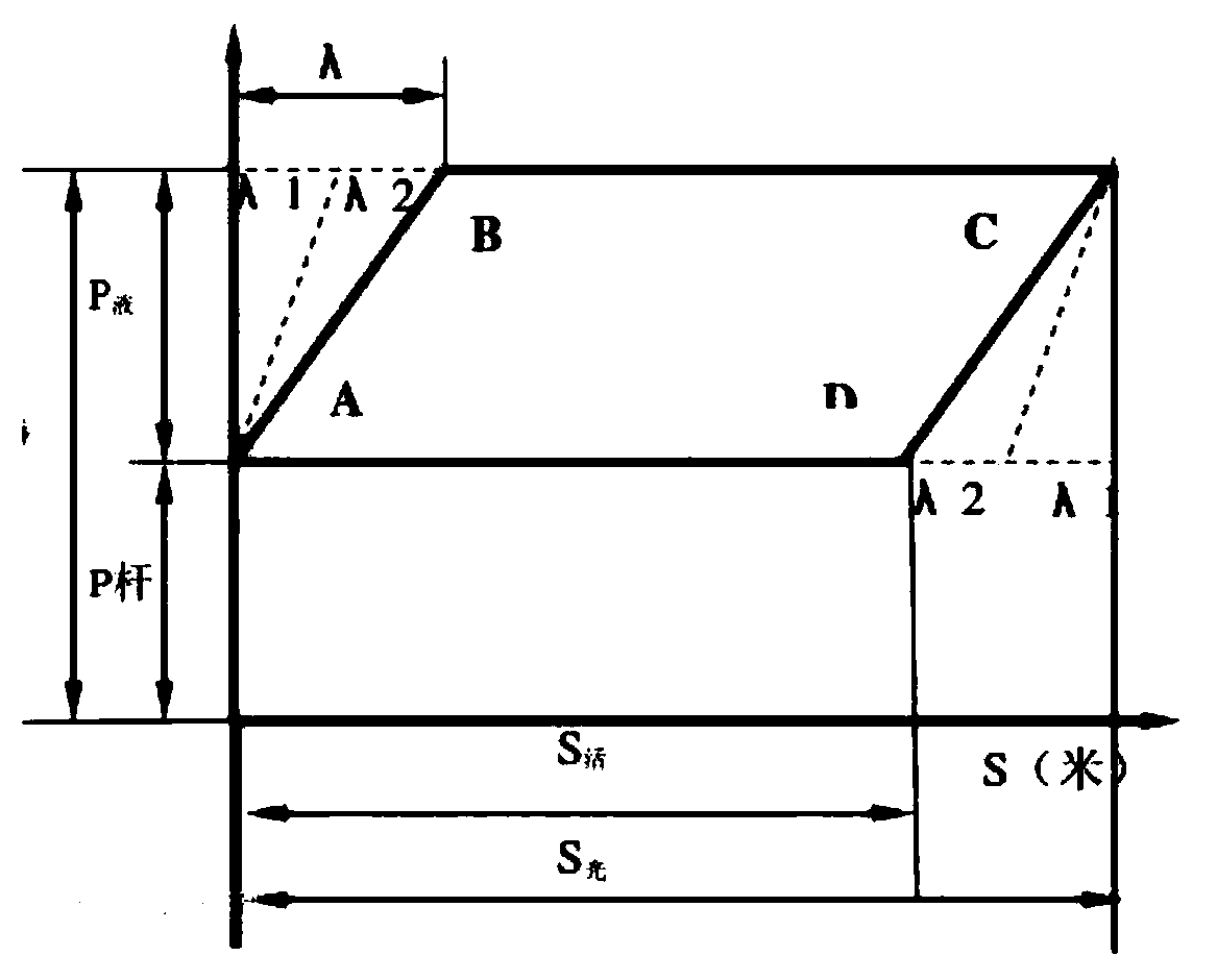
[0041] The indicator diagram is a curve describing the relationship between the suspension load of the polished rod of the pumping unit well and the stroke change, such as figure 1 As shown, the theoretical indicator diagram has the following assumptions, that is, it is assumed that the polished rod only bears the static load of the sucker rod string and the liquid column above the cross-sectional area of ​​the piston. The abscissa represents the distance of the polished rod recorded in proportion, and the ordinate represents the load on the polished rod recorded in proportion; the size of the trap area of ​​the curve indicates how much work the pump does.

[0042] Before drawing the theoretical dynamometer diagram, first, calculate the relevant basic data of the pumping unit itself; then, calculate the height of the polished rod static load on the ordinate, and the extension length of the sucke...


PUM


Abstract

The invention discloses a drawing method of a beam-pumping unit indicator diagram. A crank intersection angle and motor input power are based on, an accurate data basis is provided for drawing the indicator diagram, thus accurate drawing of the indicator diagram is realized, and then parameters of a suspension center load in the dynamic production process are accurately reflected. The drawing method includes the following implementation steps that (1) position change of a suspension center C is determined based on a crank intersection angle theta; (2) based on motor power P and the crank intersection angle theta, force change of the suspension center C is measured indirectly; and (3) the indicator diagram is drawn.

Description

Technical field [0001] The invention is a brand-new method for drawing the indicator diagram of a beam pumping unit, which is implemented based on a new four-bar linkage movement model, and belongs to the field of computer information technology for oilfield construction. Background technique [0002] At present, beam pumping units are commonly used in domestic oilfield exploration and construction fields. For the construction budget, inspection, adjustment of pumping unit balance and equipment usage in the process of crude oil production and development, indicator diagrams are usually adopted. [0003] The indicator diagram is the abbreviation of the surface indicator diagram of the pumping unit. It is a schematic diagram describing the relationship between the suspension point load of the polished rod of the pumping unit and the stroke change. The indicator diagram simplifies the work done by the change of the suspended point load of the polished rod of the pumping unit into an ...

Claims


Application Information

Patent Timeline
Patent Type & Authority Patents(China)
IPC IPC(8): E21B47/009
CPCE21B47/009
Inventor 杭柏林陈永江
Owner 青岛江林驱动科技有限公司
Features
  • R&D
  • Intellectual Property
  • Life Sciences
  • Materials
  • Tech Scout
  • Unparalleled Data Quality
  • Higher Quality Content
  • 60% Fewer Hallucinations
Learn More