Plasma Duty Flame Igniter Based on Aeroengine Afterburner

A technology of afterburner and aero-engine, applied in the field of ion flame igniter on duty, which can solve problems such as harsh working environment, complex structure, unfavorable rapid ignition, etc., to widen the ignition boundary, improve combustion efficiency, and shorten ignition delay time Effect

Active Publication Date: 2020-06-23
AIR FORCE UNIV PLA
View PDF7 Cites 0 Cited by
  • Summary
  • Abstract
  • Description
  • Claims
  • Application Information

AI Technical Summary

Problems solved by technology

[0006] The purpose of the present invention is to overcome the deficiencies in the above-mentioned prior art, and provide a plasma on-duty flame igniter based on the afterburner of an aero-engine, which effectively solves the problem of the harsh working environment and complicated structure of the afterburner of an aero-engine. , It is not conducive to the problem of stable and rapid ignition and continuous tissue combustion. It has realized the stable and rapid ignition and continuous combustion of the afterburner, greatly optimized the ignition mode of the afterburner, and carried out secondary combustion of the remaining gas in the main combustion chamber. Realized the clean emission of exhaust gas

Method used


Image

  • Plasma Duty Flame Igniter Based on Aeroengine Afterburner
  • Plasma Duty Flame Igniter Based on Aeroengine Afterburner
  • Plasma Duty Flame Igniter Based on Aeroengine Afterburner

Examples


Embodiment Construction

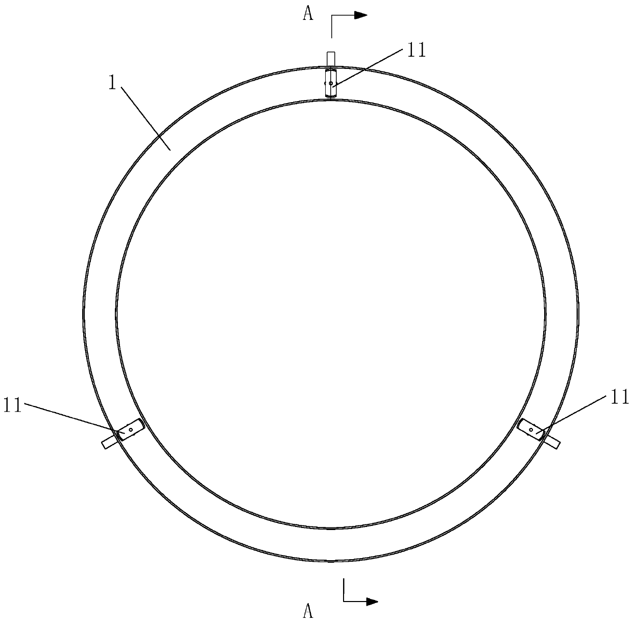
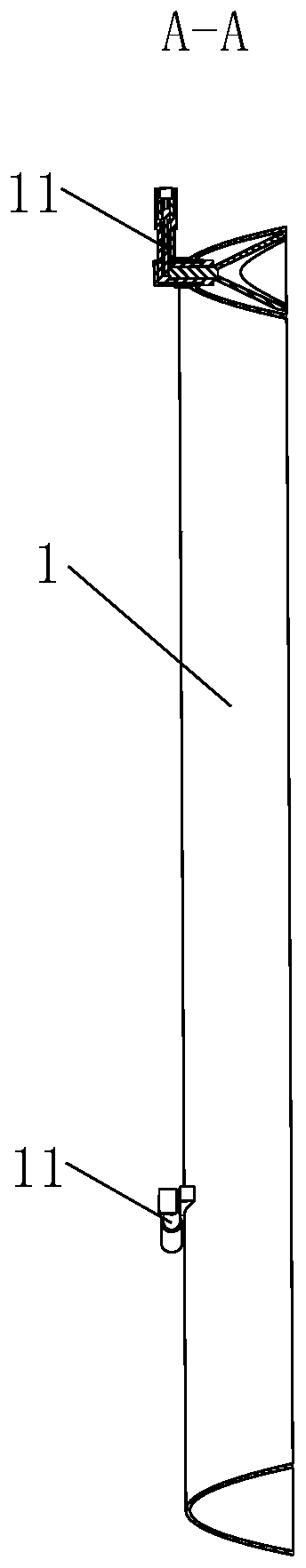
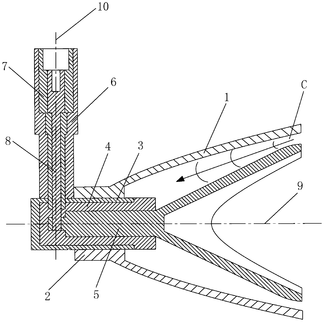
[0044] Such as Figure 1 to Figure 3 As shown, the present invention includes a flame stabilizer 1 and an embedded cathode assembly 11 installed on the flame stabilizer 1, the number of the embedded cathode assembly 11 is at least one, and the embedded cathode assembly 11 includes a connection Sleeve 2, cathode housing 3, transverse insulating tube 4, Y-shaped cathode 5, guide rod housing 6, longitudinal insulating tube 7 and energized guide rod 8, the connecting sleeve 2 is sleeved on the right side of the cathode housing 3 and the inner wall of the connecting sleeve 2 is screwed to the outer wall of the cathode casing 3, the right end of the connecting sleeve 2 is welded to the small end of the flame stabilizer 1, and the left middle part of the transverse insulating tube 4 is arranged on the cathode In the housing 3, the right end of the transverse insulating tube 4 is located outside the cathode housing 3, the closed end of the Y-shaped cathode 5 is arranged in the transve...


PUM


Abstract

The invention discloses a plasma on-duty flame igniter based on an aero-engine afterburner. The plasma on-duty flame igniter comprises a flame stabilizer and an embedded cathode combination. The embedded cathode combination comprises a connecting sleeve, a cathode shell, a transverse insulating pipe, a Y type cathode, a guide rod shell, a longitudinal insulating pipe and a power-on guide rod. Theconnecting sleeve is in threaded connection with the cathode shell, the right end of the connecting sleeve is welded to the flame stabilizer, the left middle portion of the transverse insulating pipeis arranged in the cathode shell, and the closed end of the Y type cathode is arranged in the transverse insulating pipe. The guide rod shell is vertically arranged on the top of the left side of thecathode shell, the upper middle portion of the longitudinal insulating pipe is arranged in the guide rod shell, after the lower end of the longitudinal insulating pipe penetrates through the cathode shell, the end of the longitudinal insulating pipe is located in the right portion of the transverse insulating pipe, and the upper middle portion of the power-on guide rod is arranged in the longitudinal insulating pipe. The problems that an existing aero-engine afterburner is bad in working environment and complex in structure, and stable rapid ignition and continuous organized combustion are notfacilitated.

Description

technical field [0001] The invention belongs to the technical field of aerodynamic ignition, and in particular relates to a plasma on-duty flame igniter based on an afterburner of an aeroengine. Background technique [0002] Although the mass of the aero-engine afterburner only accounts for 20% of the total mass of the engine, it is an important part to increase the thrust of the engine. The turbojet engine is equipped with an afterburner, and the thrust increase ratio reaches 40% to 50%; the turbofan engine is equipped with an afterburner, and the thrust increase ratio can reach 60% to 70% or even higher. The use of the afterburner can greatly increase the unit head-on thrust and thrust-to-weight ratio of the engine, comprehensively improve the maneuverability of the aircraft and expand the flight envelope, and improve the air superiority of the fighter. Due to the harsh working environment of the afterburner, the gas pressure is low, the flow rate is high, and the flow is...

Claims


Application Information

Patent Timeline
Patent Type & Authority Patents(China)
IPC IPC(8): F02C7/266
CPCF02C7/266F05D2240/35
Inventor 于锦禄王思博蒋永健杨犇鑫程伟达陈朝蒋陆昀胡雅骥
Owner AIR FORCE UNIV PLA
Why Eureka
Try Eureka