Lifting type gas stove

A gas stove, lift-type technology, applied in the field of stoves, can solve the problems of affecting users' cleaning of stoves, complex structure, and high product manufacturing cost

Pending Publication Date: 2019-11-12
GUANGDONG MACRO GAS APPLIANCE
View PDF0 Cites 1 Cited by
  • Summary
  • Abstract
  • Description
  • Claims
  • Application Information

AI Technical Summary

Problems solved by technology

At present, the structure of cookers on the market is poor in terms of cleaning performance, especially the disassembly and assembly of the burner and pot support on the panel is troublesome, which affects the cleaning of the cooker by users
Among them, there are basically two connection structures between the burner and the panel. One is an integral structure, which fixes the burner and the panel together, but this structure prevents users from disassembling the burner; the other is a split structure, which has the advantage of It is convenient for the user to remove the upper part of the burner, but the disadvantage is that there will be a safety hazard that the user may install the burner incorrectly and cause fire leakage, and the ignition pin and thermocouple part of this structure cannot be removed, and the above two structures cannot realize the stove. Due to the planarization effect of the panel, there will be bumps hindering the user when cleaning
Although there are some patent application schemes for liftable gas cooker structures, these liftable cookers have deficiencies in the implementation process, such as complex structures, high manufacturing costs, etc., and cannot really realize the marketization of products

Method used


Image

  • Lifting type gas stove
  • Lifting type gas stove
  • Lifting type gas stove

Examples


Embodiment 1

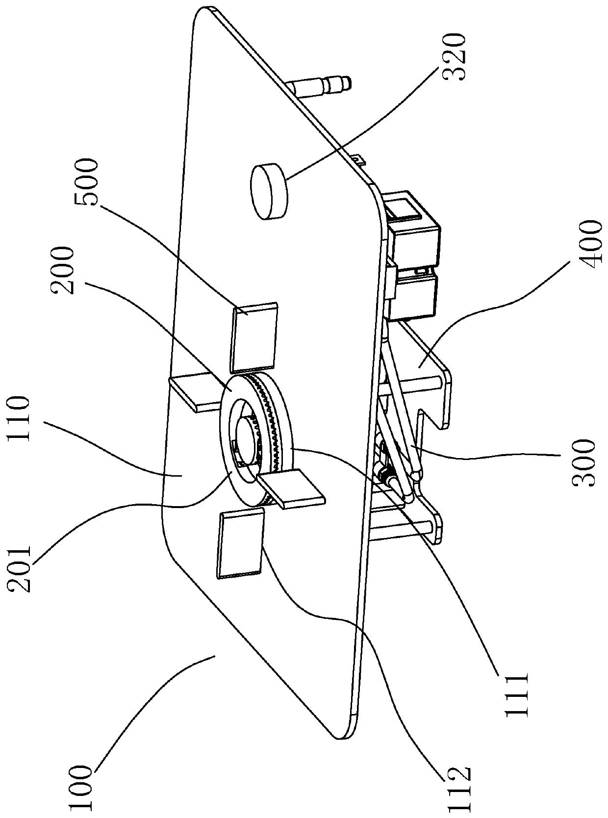
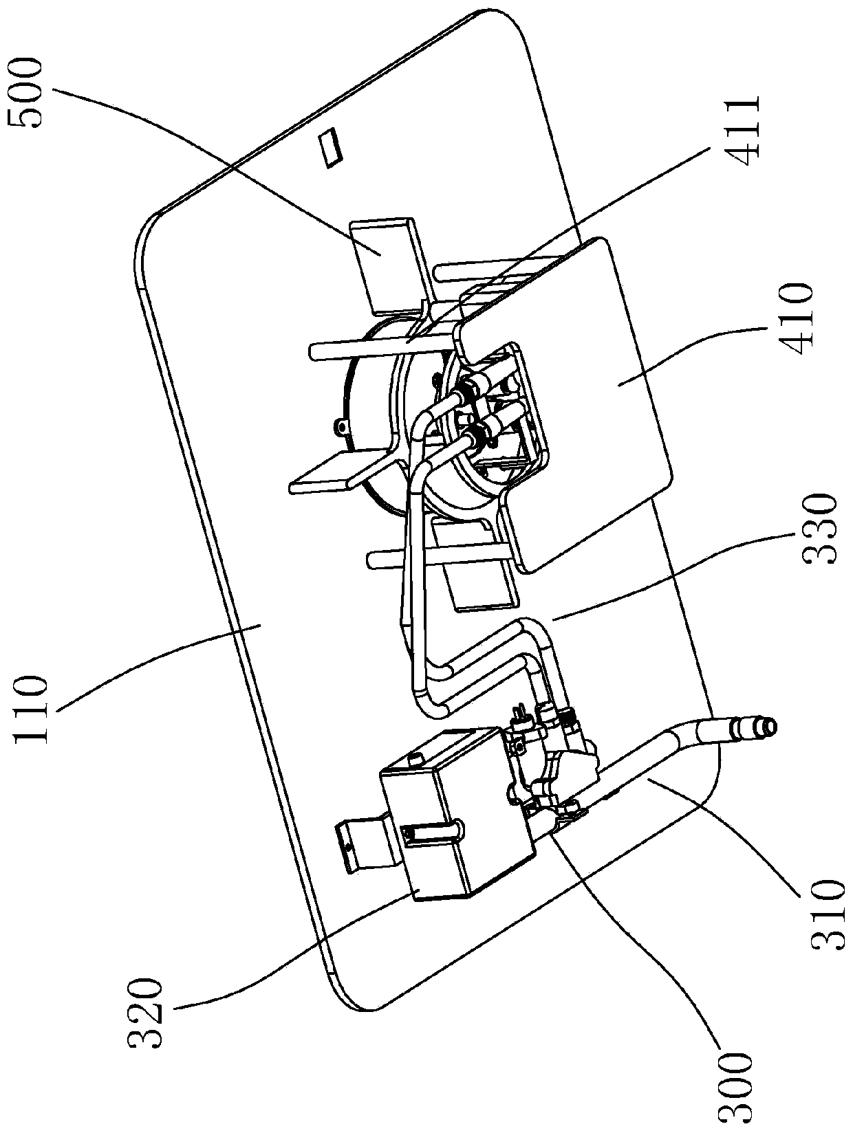
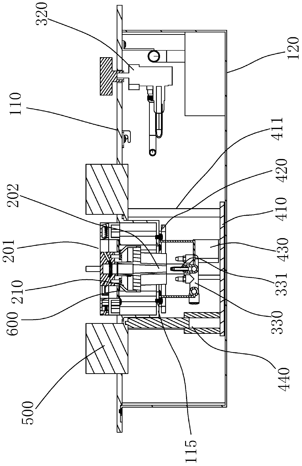
[0041] refer to Figure 1 ~ Figure 3 , a lift-type gas cooker, including a cooker body 100, the cooker body 100 includes a panel 110, a bottom case 120, a burner 200, a gas supply system 300 and a lifting device 400 are arranged inside the cooker body 100, the panel 110 is also provided with a stove frame 500 .

[0042] The panel 110 is provided with a furnace head through hole 111 and a furnace frame through hole 112 .

[0043] The gas supply system 300 is fixed in the stove body, the gas supply system 300 includes an air intake pipe 310, a switch assembly 320, and an air supply assembly 330, and the air supply assembly 330 includes a nozzle 331, and the injection direction of the nozzle 331 is up.

[0044] The lifting device 400 includes a base plate 410, a bracket 420, a drive mechanism 430, and a rack drive mechanism 440. The base plate 410 is fixed on the back of the panel 110 through a plurality of installation rods 411. The drive mechanism 430 includes a push rod moto...

Embodiment 2

[0061] see Figure 1~3 as well as Figure 11 ~ Figure 13 , a lift-type gas cooker, including a cooker body 100, the cooker body 100 includes a panel 110, a bottom case 120, a burner 200, a gas supply system 300 and a lifting device 400 are arranged inside the cooker body 100, the panel 110 is also provided with a stove frame 500 .

[0062] The panel 110 is provided with a furnace head through hole 111 and a furnace frame through hole 112 .

[0063] The gas supply system 300 is fixed in the stove body, the gas supply system 300 includes an air intake pipe 310, a switch assembly 320, and an air supply assembly 330, and the air supply assembly 330 includes a nozzle 331, and the injection direction of the nozzle 331 is up.

[0064] The lifting device 400 includes a base plate 410, a bracket 420, a drive mechanism 430, and a rack drive mechanism 440. The base plate 410 is fixed on the back of the panel 110 through a plurality of mounting rods 411. The drive mechanism 430 include...

Embodiment 3

[0077] see figure 1 , Figure 14 , a lift-type gas cooker, including a cooker body 100, the cooker body 100 includes a panel 110, a bottom case 120, a burner 200, a gas supply system 300 and a lifting device 400 are arranged inside the cooker body 100, the panel 110 is also provided with a stove frame 500 .

[0078] The gas supply system 300 is fixed in the cooker body, the gas supply system 300 includes an air intake pipe 310, a switch assembly 320, and an air supply assembly 330, the air supply assembly 330 includes a nozzle 331, and the nozzle 331 is installed on the bottom On the side of the shell 120, the jetting direction of the nozzle 331 is horizontal to the right.

[0079] The panel 110 is provided with a furnace head through hole 111 and a furnace frame through hole 112 .

[0080] The burner 200 includes a burner head 201 and an ejector tube 202. The burner head 201 is located directly below the through hole 111 of the burner head. The burner 200 is installed in t...


PUM


Abstract

The invention discloses a lifting type gas stove which comprises a stove body. The stove body comprises a panel; a combustor is arranged in the stove body; a lifting device and a nozzle are arranged in the stove body; a furnace end through hole is formed in the panel; the combustor comprises a furnace end and an injection pipe; the lifting device drives the combustor to lift up and down; the nozzle is fixed onto the stove body; the axial direction of the injection pipe is the vertical direction; the injection pipe comprises a gas inlet end; the nozzle directly faces the gas inlet end of the injection pipe; and when the combustor is lifted up to be in place, the nozzle faces the gas inlet end of the injection pipe; and a gap for air to enter is arranged between the gas inlet end and the nozzle. According to the lifting type gas stove provided by the invention, the lifting device is utilized for driving the combustor to lift up and down, so that the stove has a favorable plane effect; and meanwhile, a gas circuit design in the gas stove is optimized, so that the lifting type gas stove provided by the invention is simple, convenient and reasonable in structure, stable in gas supply, and convenient for product marketization.

Description

technical field [0001] The invention relates to a cooker, especially a gas cooker. Background technique [0002] The cookers currently on the market generally include a panel, a bottom case, a burner disposed in the bottom case, and a hob installed on the panel. The cooker structure currently on the market is relatively poor in terms of cleaning performance, especially the disassembly and assembly of the burner and the pot support on the panel is cumbersome, which affects the cleaning of the cooker by users. Among them, there are basically two connection structures between the burner and the panel. One is an integral structure, which fixes the burner and the panel together, but this structure prevents users from disassembling the burner; the other is a split structure, which has the advantage of It is convenient for the user to remove the upper part of the burner, but the disadvantage is that there will be a safety hazard that the user may install the burner incorrectly and...

Claims


Application Information

Patent Timeline
Patent Type & Authority Applications(China)
IPC IPC(8): F24C3/08
CPCF24C3/085
Inventor 艾穗江梁迪燊刘兵何也童芳
Owner GUANGDONG MACRO GAS APPLIANCE
Why Eureka
Try Eureka