Heat exchange structure of gas dryer

A technology of gas drying and heat exchange structure, which is applied in the direction of heat exchanger shell, heat exchange equipment, lighting and heating equipment, etc., which can solve the problems of easy freezing of condensed water, complicated manufacturing process and high cost, and improve the utilization of cooling capacity High efficiency, simple overall structure and low production cost

Pending Publication Date: 2019-11-12
FOSHAN TIANDI YUANYI PURIFICATION EQUIP
View PDF0 Cites 0 Cited by
  • Summary
  • Abstract
  • Description
  • Claims
  • Application Information

AI Technical Summary

Problems solved by technology

[0002] The existing heat exchange structures of compressed air dryers mainly fall into the following categories: the first category is the heat exchange structure of refrigerated dryers, such as Figure 5 As shown, 1a-cooling and heat exchanger, 2a-evaporator, 3a-gas-liquid separator are made of separate barrels, the structure is complicated, the production is complicated, and the volume is huge. The evaporator adopts copper-aluminum fin type or stainless steel fin type. Heater, the gap between the fins is small, the condensed water is easy to freeze in the evaporator, resulting in ice blockage
The second type, plate or plate-fin type cold dryer heat exchanger, such as Image 6 As shown, this heat exchange structure has the following problems: 1. Aluminum plate-fin heat exchangers or stainless steel plate heat exchangers are used for cold and heat exchange and evaporators, and the welding joints are easy to leak and cannot be repaired; 2. The plates are thin , is also easy to corrode and perforate and cannot be repaired; 3. Due to the small size, the steam-water separation effect is not good; if an external steam-water separator is installed, the compact structure cannot be achieved; 4. The gap between the plates is small, and it is easy to be blocked by dirt. The accumulation of more dirt will affect the heat exchange effect, and the resistance will increase, which will cause an increasing pressure difference between the inlet and outlet of the compressed air, and the condensed water will easily freeze in the evaporator to block the compressed air channel, resulting in ice blockage; 5. The production is complicated, only professional plate or plate-fin heat exchanger manufacturers can make it, and the cost is high
The third category is a cold dryer with a cold heat exchanger and an evaporator built in a bucket, such as Figure 7 As shown in the figure: a-refrigerant inlet, b-refrigerant outlet, h-air inlet, i-air outlet, g-spiral tube, e-filter net, f-evaporator, the evaporator uses copper and aluminum fins Type or stainless steel fin heat exchanger, this structure has the following problems: 1) the fin gap is small, the condensed water is easy to freeze in the evaporator, resulting in ice blockage; 2) there is no special gas-liquid separation device, and It relies on natural gravity for water analysis, and the water is easily taken away by the air flow, and the gas-water separation effect is not good; 3) The production precision is high, the production process is complicated, and the cost is high
[0003] To sum up, the existing compressed air dryers have unsatisfactory heat transfer structures, high cost, prone to ice blockage, and low heat transfer efficiency

Method used


Image

  • Heat exchange structure of gas dryer
  • Heat exchange structure of gas dryer
  • Heat exchange structure of gas dryer

Examples


Embodiment 1

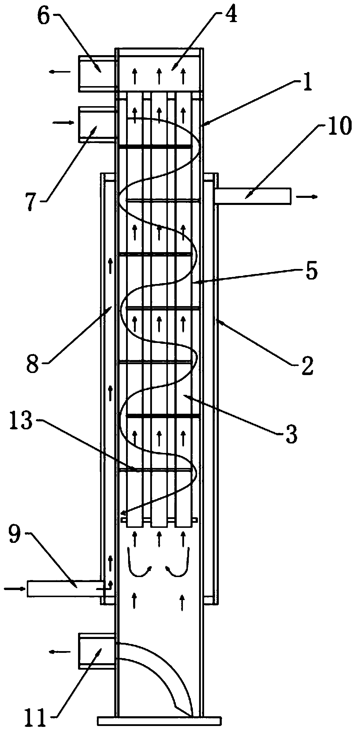
[0021] Embodiment 1: as figure 1 As shown, the heat exchange structure of a gas dryer described in this embodiment, which can be used to filter compressed air and gas, includes a vertically arranged first tube 1 and a sleeve on the outside of the first tube 1 In the second tube 2, more than one third tube 3 is arranged in the cavity of the first tube 1 along its length direction, and these third tubes 3 are evenly distributed. Both the top and the bottom of the first tube 1 and the second tube 2 are sealed, and the upper part of the inner cavity of the first tube 1 is sealed to form a first inner cavity 4 at the top and a second inner cavity 5 at the bottom. The first inner cavity 4 and the second inner cavity 5 are separated from each other, and a gas outlet 6 and a gas inlet 7 connected to the outside world are respectively provided above and below the sealing place, and the gas inlet 7 and the gas outlet 6 are opened along the horizontal direction. The gas inlet 7 communi...

Embodiment 2

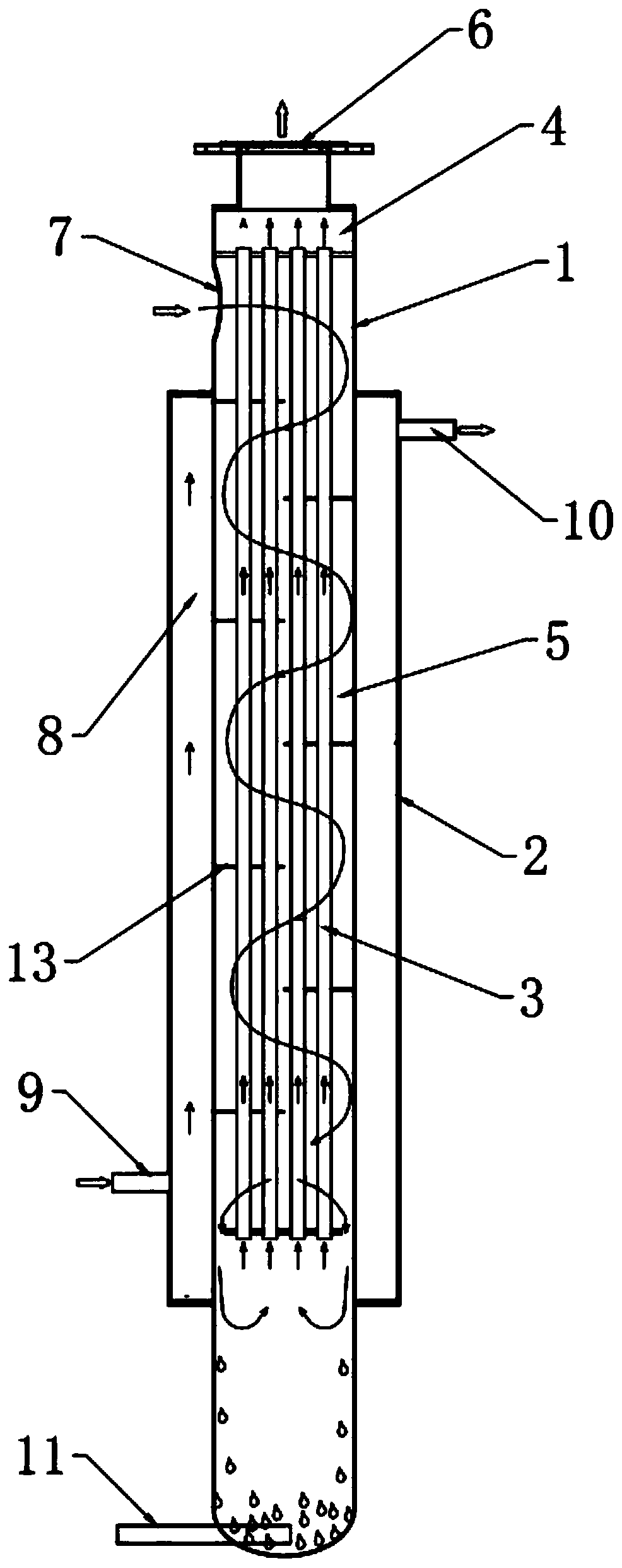
[0023] Embodiment 2: refer to figure 2 , Compared with Embodiment 1, the difference is that: the gas inlet 7 is arranged to open in the horizontal direction, and the gas outlet 6 is arranged to open upward.

Embodiment 3

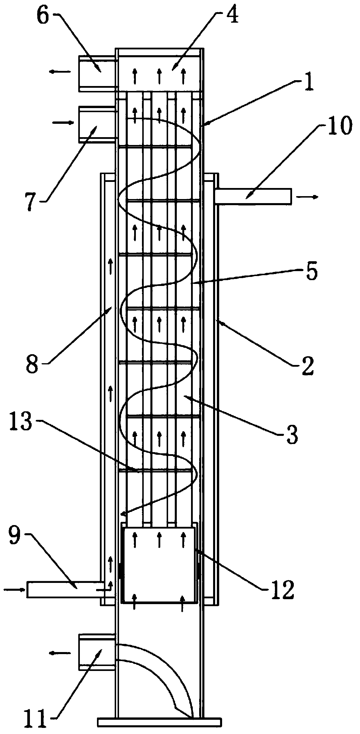
[0024] Embodiment 3: refer to image 3 , with respect to embodiment 1, its difference is: the bottom end of described third pipe 3 is connected with the fourth pipe 12 of " 冂 " type section, and the top of fourth pipe 12 is sealed, and the bottom is open, and described third pipe 3 The bottom end passes through the top of the fourth tube 12 and communicates with the second inner cavity 5. The fourth tube 12 is preferably coaxially arranged with the first tube 1, and the outer wall of the fourth tube 12 is connected with the first tube 1. A channel is formed between the inner walls of the first tube 1 to force the gas to flow against the inner wall of the first tube 1. The position of the fourth tube 12 is within the length of the second tube 2, because the third inner chamber 8 has refrigerant, and the second The gas in the inner cavity 5 flows close to the inner wall of the first tube 1, and the distance between the gas and the refrigerant is short, and the heat exchange effe...


PUM


Abstract

The invention provides a heat exchange structure of a gas dryer. The heat exchange structure of the gas dryer comprises a first tube arranged vertically and a second tube arranged outside the first tube in a sleeving mode. An inner cavity of the first tube is internally provided with one or more third tubes, and the top and the bottom of the first tube and the top and the bottom of the second tubeare sealed, and the upper part of the inner cavity of the first tube is sealed to form a first inner cavity which is located at the upper portion and a second inner cavity which is located at the lower portion. A gas outlet and a gas inlet are arranged above and below the sealed portion respectively. One ends of the third tubes communicate with the first inner cavity, and the other ends of the third tubes communicate with the lower part of the second inner cavity. A third inner cavity is formed between the outer wall of the first tube and the inner wall of the second tube. The third inner cavity is provided with a refrigerant inlet allowing a refrigerant to be fed and a refrigerant outlet allowing the refrigerant to be discharged, and the bottom of the second inner cavity communicates with a liquid outlet. The heat exchange structure of the gas dryer has the advantages of having a compact structure, reducing of ice blocking phenomena, being simple in process, being low in cost, havinga good heat exchange effect, having a high cooling energy utilization rate and a good gas-liquid separation effect.

Description

technical field [0001] The invention relates to the technical field of heat exchangers, in particular to a heat exchange structure of a gas dryer. Background technique [0002] The existing heat exchange structures of compressed air dryers mainly fall into the following categories: the first category is the heat exchange structure of refrigerated dryers, such as Figure 5 As shown, 1a-cooling and heat exchanger, 2a-evaporator, 3a-gas-liquid separator are made of separate barrels, the structure is complicated, the production is complicated, and the volume is huge. The evaporator adopts copper-aluminum fin type or stainless steel fin type. Heater, the gap between the fins is small, the condensed water is easy to freeze in the evaporator, resulting in ice blockage. The second type, plate or plate-fin type cold dryer heat exchanger, such as Figure 6 As shown, this heat exchange structure has the following problems: 1. Aluminum plate-fin heat exchangers or stainless steel plate...

Claims


Application Information

Patent Timeline
Patent Type & Authority Applications(China)
IPC IPC(8): F28B1/02F28B9/08F28F9/22B01D53/26
CPCB01D53/265F28B1/02F28B9/08F28F9/22
Inventor 廖志远
Owner FOSHAN TIANDI YUANYI PURIFICATION EQUIP
Why Eureka
Try Eureka