Target recognition method based on multi-source image joint shape analysis and multi-attribute fusion

A target recognition and multi-attribute technology, applied in the field of remote sensing image target detection and recognition, can solve the problem of low accuracy of ship target recognition and achieve the effect of improving the recognition accuracy

Active Publication Date: 2019-11-12
HARBIN INST OF TECH
View PDF9 Cites 8 Cited by
  • Summary
  • Abstract
  • Description
  • Claims
  • Application Information

AI Technical Summary

Problems solved by technology

[0006]The purpose of the present invention is to solve the problem of low accuracy rate of existing ship target recognition, and propose a target recognition based on multi-source image joint shape analysis and multi-attribute fusion method

Method used


Image

  • Target recognition method based on multi-source image joint shape analysis and multi-attribute fusion
  • Target recognition method based on multi-source image joint shape analysis and multi-attribute fusion
  • Target recognition method based on multi-source image joint shape analysis and multi-attribute fusion

Examples


specific Embodiment approach 1

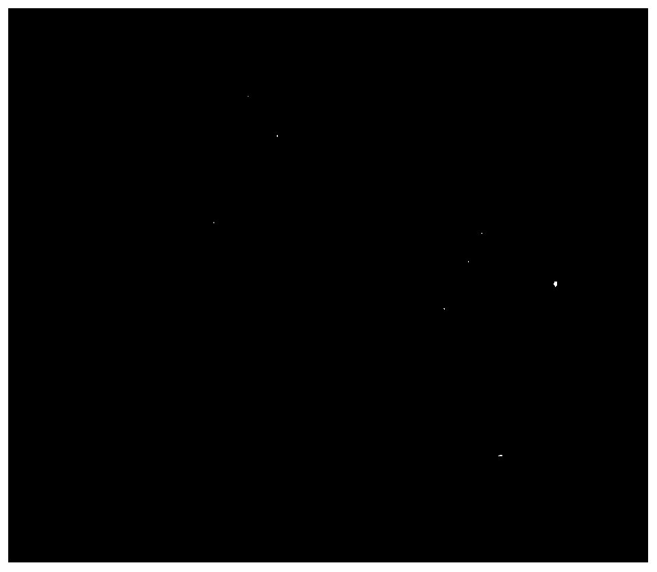
[0053] Specific implementation mode one: combine figure 1This embodiment is described. The specific process of the target recognition method based on multi-source image joint shape analysis and multi-attribute fusion in this embodiment is as follows:

[0054] Step 1. Manually register (in order to make the acquired optical remote sensing image and SAR remote sensing image have the same target position) optical remote sensing image and SAR remote sensing image, only use optical remote sensing image for line detection, and obtain a large number of slices of suspected ships docking at the dock , and according to the straight line angle, rotate the dock slice to the horizontal;

[0055] Step 2. Carry out joint shape analysis on the optical remote sensing image and SAR remote sensing image of the horizontal wharf slice to obtain the coordinates of the suspected ship, that is, obtain the length and width information of the ship, and extract the suspected ship slice corresponding to ...

specific Embodiment approach 2

[0060] Specific implementation mode two: combination Figure 2a , 2b This embodiment is described. The difference between this embodiment and the specific embodiment 1 is that in the first step, the optical remote sensing image and the SAR remote sensing image are manually registered, and only the optical image is used for line detection to obtain a large number of suspected ships docking at the dock. Slice, and according to the angle of the line, rotate the dock to slice horizontally; the specific process is:

[0061] Step 11. Manually register the optical remote sensing image and the SAR remote sensing image. On the optical remote sensing image, according to the principle of uniform gray distribution information around any point, select the seed point on the sea surface. The selection of the seed point should satisfy the following formula:

[0062]

[0063] The point that satisfies the attribute P(x,y) is the seed point, where U represents the neighborhood, I is the gray...

specific Embodiment approach 3

[0067] Embodiment 3: The difference between this embodiment and Embodiment 1 or 2 is that in the second step, the joint shape analysis is performed on the optical remote sensing image and the SAR remote sensing image of the horizontal wharf slice to obtain the coordinates of the suspected ship and extract the corresponding coordinates The suspected ship slice; the specific process is:

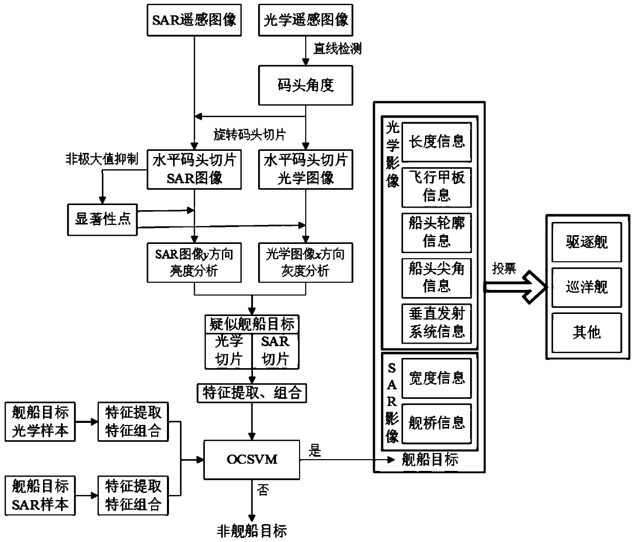
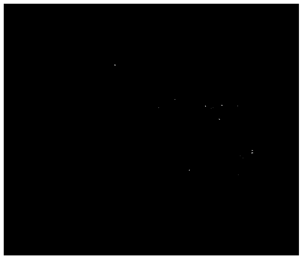
[0068] Step 21. Slicing in the optical and SAR docks rotated to the horizontal (eg Figure 4a , 4b ) to detect ship targets, first use SAR images to quickly determine salient points through non-maximum suppression (such as Figure 4c , 4d ), and then perform grayscale analysis on the x-direction of each salient point in the optical image to find the intersection points of the bow, stern and seawater (such as Figure 5a , 5b ), so as to obtain the abscissa of the ship;

[0069] Step 2 and 2. Reuse 100 pixels on the left and right sides of each salient point in the SAR image (with each salie...


PUM


Abstract

The invention discloses a target recognition method based on multi-source image joint shape analysis and multi-attribute fusion, and relates to a multi-source image target recognition method. The objective of the invention is to solve the problem of low accuracy of existing ship target identification. The method comprises: 1, obtaining a large number of suspected ship berthing wharf slices, and rotating the wharf slices to be horizontal according to the linear angle; 2, obtaining suspected ship coordinates, and extracting suspected ship slices corresponding to the coordinates; 3, classifying the suspected ship into a ship target and a non-ship target; 4, extracting optical slices from the targets classified into the ships, respectively detecting flight deck types, bow sharp corner positions, bow contour types and vertical launcher positions, extracting SAR slices, and detecting bridge positions; 5, performing multi-attribute fusion ship model identification; and 6, taking the class with the maximum voting result as a ship model identification result. The method is applied to the technical field of remote sensing image target detection and recognition.

Description

technical field [0001] The invention belongs to the technical field of remote sensing image target detection and recognition, and in particular relates to a multi-source image target recognition method. Background technique [0002] With the rapid development and innovation of related disciplines such as sensor technology, wireless communication technology and aerospace technology in recent years, a large number of optical remote sensing satellites and synthetic aperture radar (Synthetic Aperture Radar, SAR) satellites have been successfully launched and operated around the world. At present, there are 438 earth remote sensing satellites in orbit in the world. China has the most large remote sensing satellites, with a total of 84, such as Gaofen series, resource series, Gaojing 1, Jilin 1, etc.; while the United States and the European Union have 50 each And 49 large remote sensing satellites and about 150 small remote sensing satellites, such as Quickbird, Ikonos, WorldView...

Claims


Application Information

Patent Timeline
Patent Type & Authority Applications(China)
IPC IPC(8): G06K9/00G06K9/34G06K9/46G06K9/62
CPCG06V20/13G06V10/267G06V10/464G06F18/2411
Inventor 陈浩陈稳高通
Owner HARBIN INST OF TECH
Why Eureka
Try Eureka