Coil frame for clapper-type relay and clapper-type relay
A technology of relays and bobbins, applied in the direction of relays, electromagnetic relays, detailed information of electromagnetic relays, etc., can solve problems affecting the stability, durability, safety, and aggravation of snap-in relays, and achieve the effect of simple structure and safe service
- Summary
- Abstract
- Description
- Claims
- Application Information
AI Technical Summary
Problems solved by technology
Method used
Image
Examples
Embodiment 1
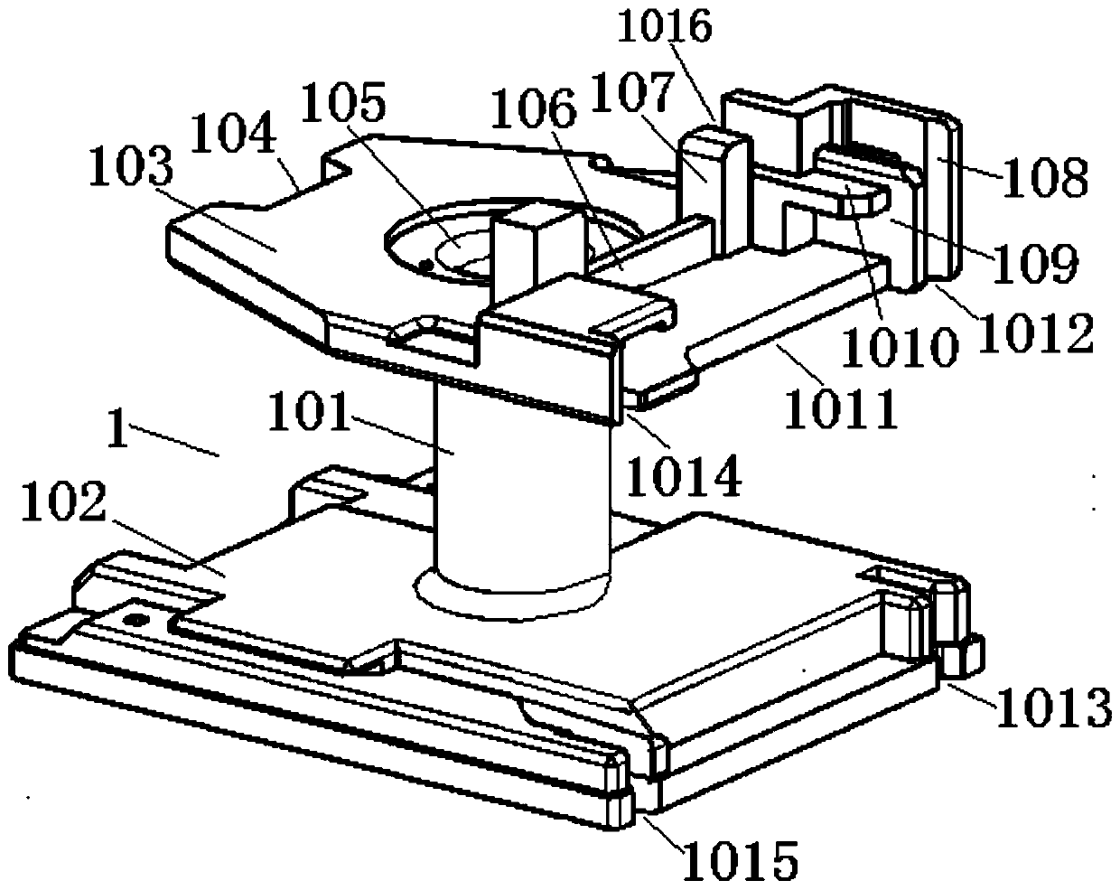
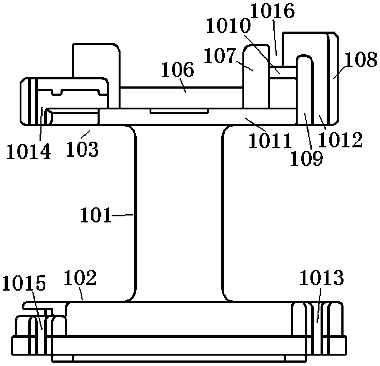
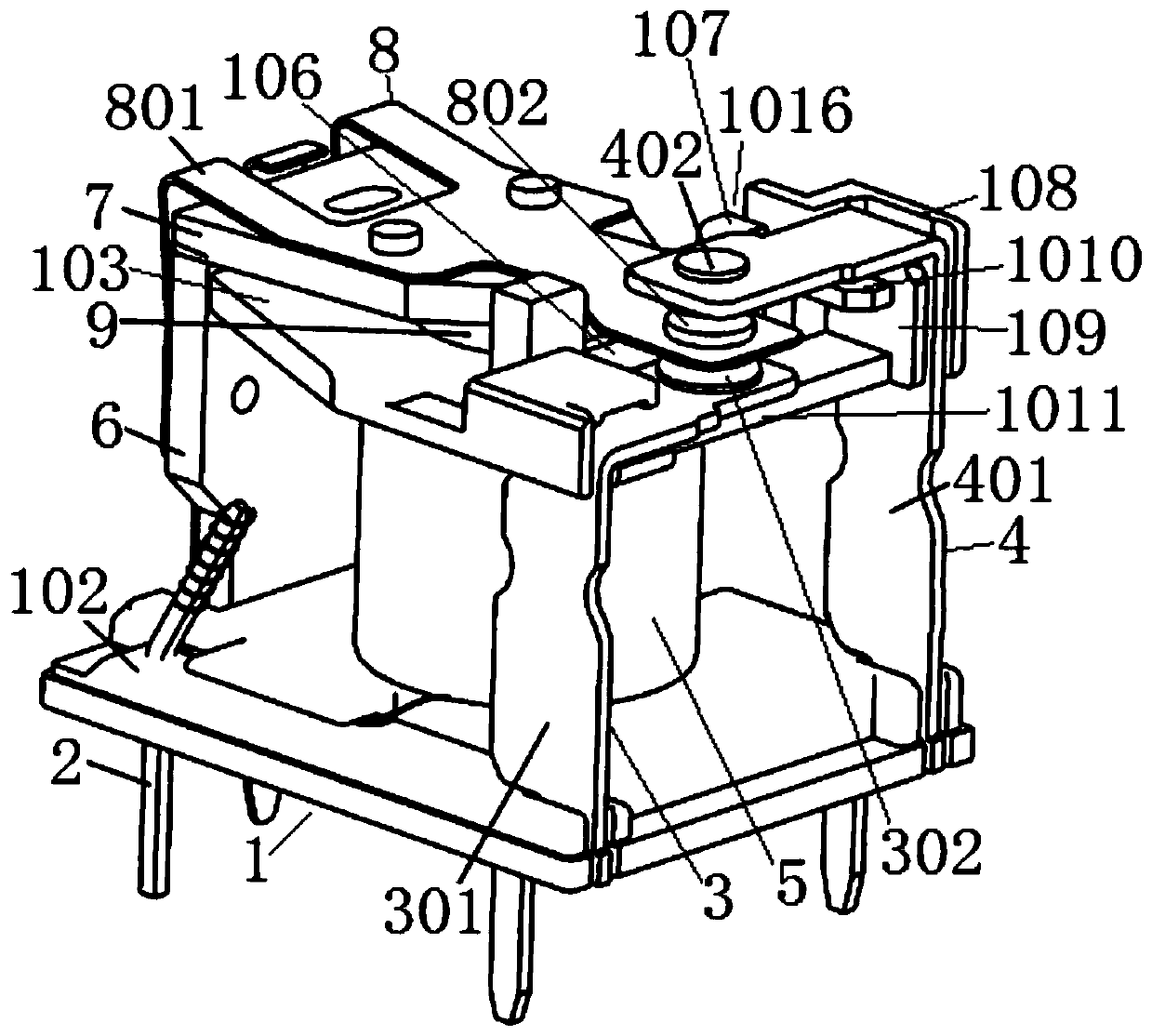
[0034] see figure 1 and figure 2 As shown, the bobbin 1 of the present invention includes a bobbin 101 and a coil baffle 1 102 and a coil baffle 2 103 at both ends of the bobbin 101, and the corresponding areas in the bobbin 102 and the coil baffles at both ends It has an axial core assembly hole 105 . Coil baffle 1 102 is used to arrange the coil pins, the pin ends of the static spring part, the pin ends of the moving spring part, the yoke and other parts, and it is used as the bottom side baffle in the customary thinking. Coil baffle 2 103 is used as the pole shoe for arranging the iron core and cooperates with the clapping action of the armature on the top, the contact cooperation between the static spring part and the moving spring part, etc., and is used as the top side baffle in the customary thinking.
[0035] The top of the coil baffle plate 2 103 on the side of the iron core assembly hole 105 (including the iron core assembly hole 105) is used to arrange the armatu...
Embodiment 2
[0053] The bobbin of the present invention includes a bobbin and coil baffles 1 and 2 at both ends of the bobbin. The inside of the bobbin and the corresponding areas of the coil baffles at both ends have axial iron core assembly holes. The coil baffle is used to arrange the coil pins, the pin ends of the static spring part, the pin ends of the moving spring part, the yoke and other components, and it is used as the bottom side baffle in the customary thinking. Coil baffle 2 is used as the pole shoe for arranging the iron core and cooperates with the clapping action of the armature on the top, the contact cooperation between the static spring part and the moving spring part, etc., and is used as the top side baffle in the customary thinking.
[0054] The top of coil baffle plate 2 (including the core assembly hole) on the side of the iron core assembly hole is used for arranging the armature, and the outer edge of the area where the coil baffle plate 2 arranges the armature has...
Embodiment 3
[0068] The bobbin of the present invention includes a bobbin and coil baffles 1 and 2 at both ends of the bobbin. The inside of the bobbin and the corresponding areas of the coil baffles at both ends have axial iron core assembly holes. The coil baffle is used to arrange the coil pins, the pin ends of the static spring part, the pin ends of the moving spring part, the yoke and other components, and it is used as the bottom side baffle in the customary thinking. Coil baffle 2 is used as the pole shoe for arranging the iron core and cooperates with the clapping action of the armature on the top, the contact cooperation between the static spring part and the moving spring part, etc., and is used as the top side baffle in the customary thinking.
[0069] The top of coil baffle plate 2 (including the core assembly hole) on the side of the iron core assembly hole is used for arranging the armature, and the outer edge of the area where the coil baffle plate 2 arranges the armature has...
PUM
 Abstract
Description
Claims
Application Information
 - R&D
- Intellectual Property
- Life Sciences
- Materials
- Tech Scout
- Unparalleled Data Quality
- Higher Quality Content
- 60% Fewer Hallucinations
Browse by: Latest US Patents, China's latest patents, Technical Efficacy Thesaurus, Application Domain, Technology Topic, Popular Technical Reports.
© 2025 PatSnap. All rights reserved.Legal|Privacy policy|Modern Slavery Act Transparency Statement|Sitemap|About US| Contact US: help@patsnap.com


