Cable intermediate joint protection shell

A technology for cable intermediate joints and protective shells, applied in cable joints and other directions, can solve problems such as low yield, cracking, and falling off of lead seals of protective shells.

Active Publication Date: 2019-11-12
SHENZHEN POWER SUPPLY BUREAU
View PDF9 Cites 2 Cited by
  • Summary
  • Abstract
  • Description
  • Claims
  • Application Information

AI Technical Summary

Problems solved by technology

However, the quality of the lead sealing process depends largely on the technical level of the staff and is easily affected by factors such as the installation environment, lead sealing time, and spray gun flame temperature, resulting in low yields and frequent failures after the line has been running for a period of time. The lead seal of the protective shell falls off, the cable joint gets water, and it is prone to cracking, which leads to the failure of the cable joint seal

Method used


Image

  • Cable intermediate joint protection shell
  • Cable intermediate joint protection shell
  • Cable intermediate joint protection shell

Examples


Embodiment Construction

[0031] The present invention will be described in detail below with reference to the accompanying drawings and specific embodiments.

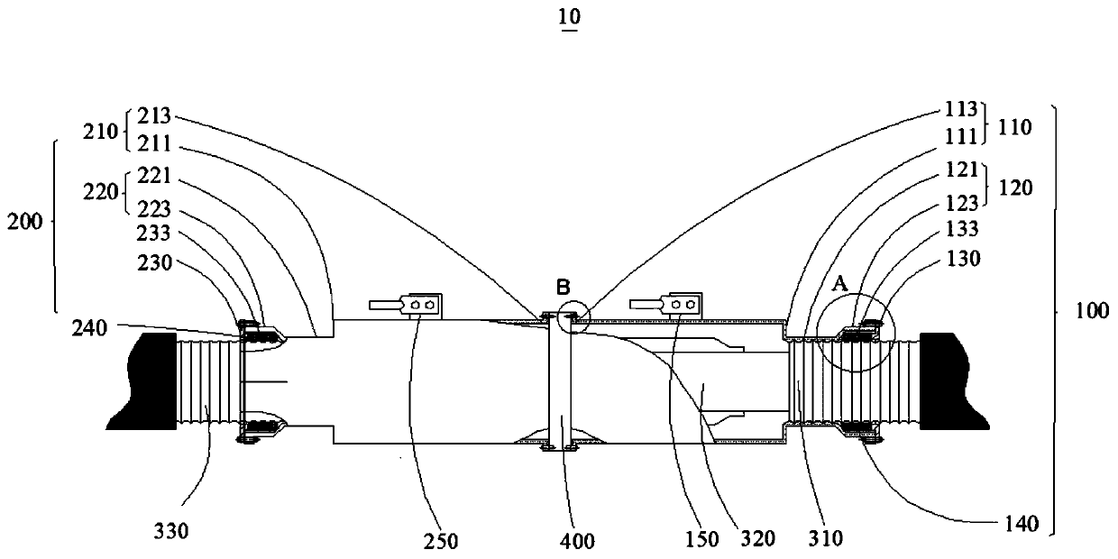
[0032] see figure 1 with figure 2 As shown, a schematic structural view of the cable intermediate joint protective shell 10 in an embodiment of the present application, the cable intermediate joint protective shell 10 includes a first sealing assembly 100 and a second sealing assembly 200 with the same structure;

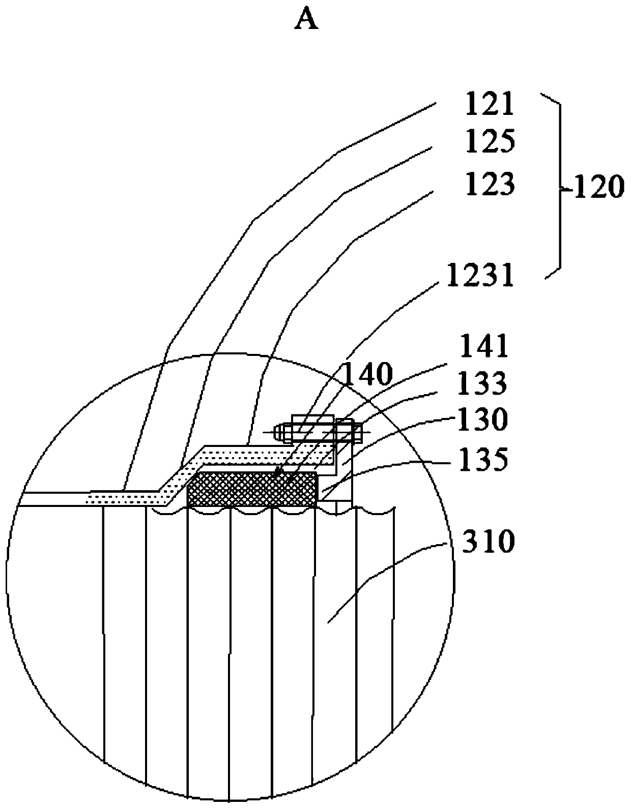
[0033] The first sealing assembly 100 includes a first sealing tube 110 , a second sealing tube 120 and a fastening flange 130 . The second sealing assembly 200 includes a first sealing tube 210 , a second sealing tube 220 and a fastening flange 230 . The structure and connection method of the second sealing assembly 200 are the same as those of the first sealing assembly 100 .

[0034] In one embodiment, the first sealing tube 110 of the first sealing assembly 100 is used to accommodate the cable intermediate joint 320 , and the...


PUM


Abstract

The invention relates to a cable intermediate joint protection shell; the cable intermediate joint protection shell comprises a first sealing assembly and a second sealing assembly, wherein the firstsealing assembly and the second sealing assembly are the same in structure. The first sealing assembly is in sealing connection with the second sealing assembly. The connecting pipe of the first sealing assembly is provided with an internal thread, wherein the internal thread is used for being matched with the external thread of a metal sheath of a first cable. The two ends of the cable intermediate joint protection shell can be stably connected with the metal sheath of the first cable and the metal sheath of a second cable, the contact area is large, and the conduction resistance is small. Afastening flange of the first sealing assembly is used for sleeving the metal sheath of the first cable and is arranged at one end, far away from the connecting pipe, of the sealing shell, and the fastening flange is connected with a second flange end in a bolt mode, so that a sealing cavity is formed among the sealing shell and the fastening flange and the metal sheath of the first cable; and thesealing cavity is used for filling a sealing element. The sealing process is simple, and is not limited by the technical level of operating workers during on-site installation.

Description

technical field [0001] The invention relates to a cable joint sealing device, in particular to a cable intermediate joint protective shell. Background technique [0002] A protective shell is required outside the main body of the cable intermediate joint. The protective shell must not only be reliably connected to the cable metal sheath, but also ensure that the structural level of the cable intermediate joint is similar to that of the cable, and realize metal shielding and mechanical protection functions. At the same time, it must be reliably sealed with the metal sheath to prevent external water vapor from entering the protective shell and causing breakdown of the main body of the intermediate joint. At present, the cable intermediate joint protective shell mainly uses the lead-sealing process to realize the electrical connection and sealing structure with the cable metal sheath. However, the quality of the lead sealing process depends largely on the technical level of th...

Claims


Application Information

Patent Timeline
Patent Type & Authority Applications(China)
IPC IPC(8): H02G15/18
CPCH02G15/18
Inventor 詹威鹏
Owner SHENZHEN POWER SUPPLY BUREAU
Why Eureka
Try Eureka