

Control method and device for display state of Bluetooth equipment and terminal equipment
A bluetooth device and display status technology, applied in hardware monitoring, short-distance communication services, instruments, etc., can solve the problems of not being able to display user-defined status, simple display status, etc.
- Summary
- Abstract
- Description
- Claims
- Application Information
AI Technical Summary
Problems solved by technology
Method used
Image

Examples
Embodiment 1
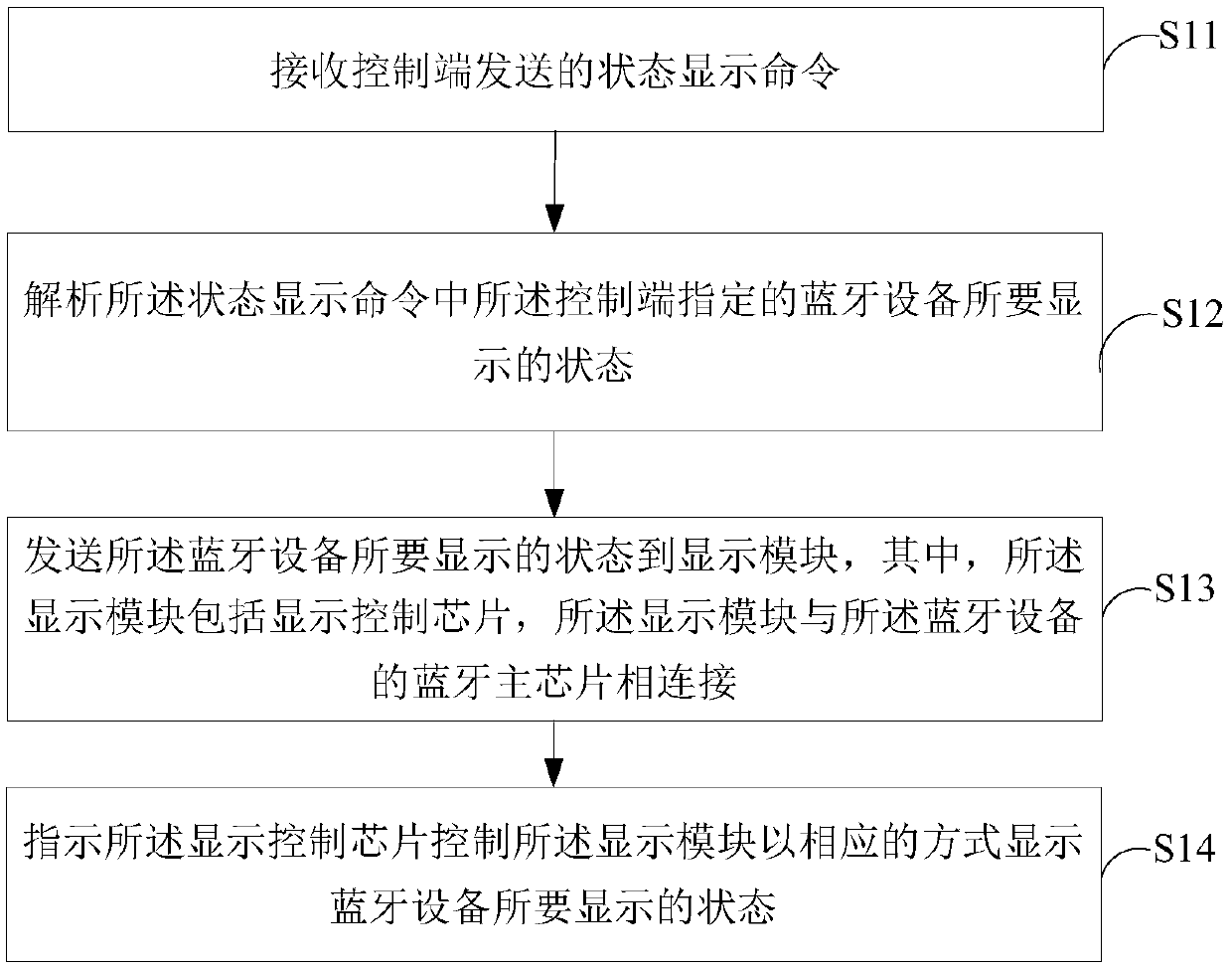
[0026] figure 1 It shows a schematic flowchart of an interaction method for a smart speaker provided in the embodiment of the present application, and is described in detail as follows:
[0027] Step S11, receiving the status display instruction sent by the control terminal;
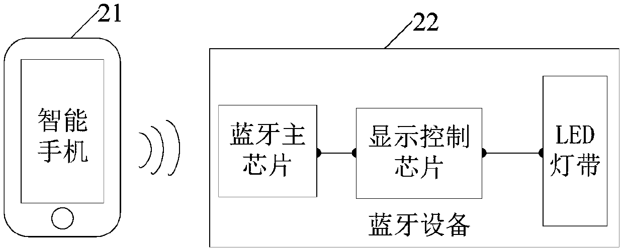
[0028] In the embodiment of the present application, the Bluetooth device receives the status display instruction sent by the control terminal; wherein, the control terminal includes a terminal device with Bluetooth function such as a smart phone, a tablet computer, and a smart wearable device. The status display instruction is used to instruct the bluetooth device to display the current status in the process of connecting with the control terminal or after successful connection.
[0029] Further, when the control terminal sends the status display instruction to the Bluetooth device, the Bluetooth device currently displays the status information through the Bluetooth serial port protocol (Serial Port Pr...
Embodiment 2
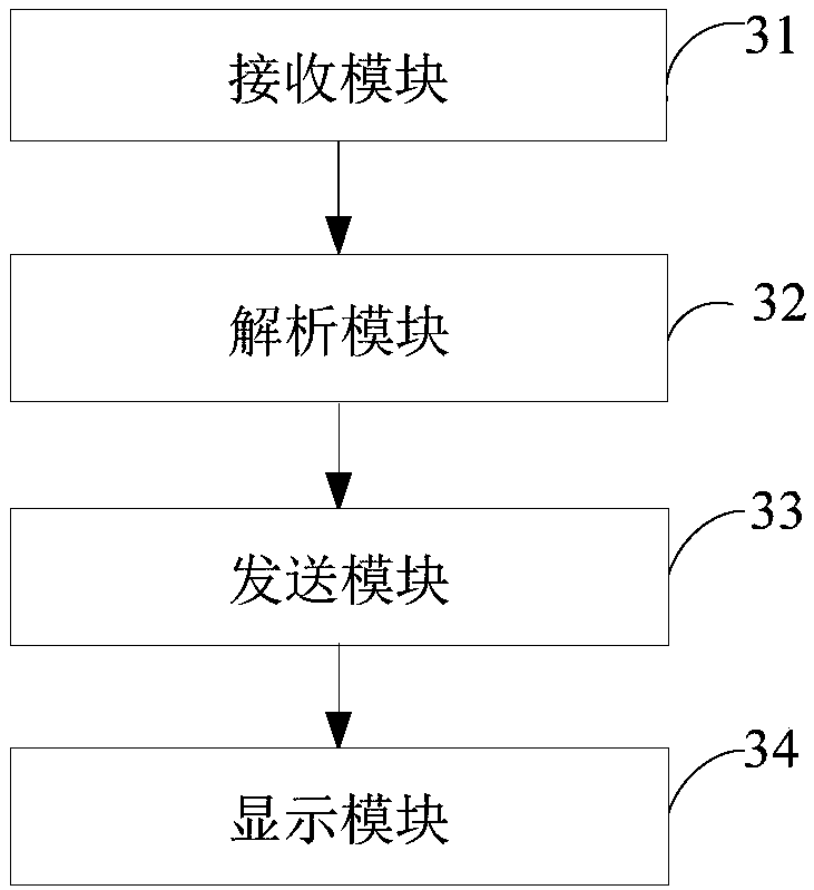
[0059] Corresponding to the interaction method of the smart speaker described in the above embodiment, image 3 A structural block diagram of an interaction device for a smart speaker provided in an embodiment of the present application is shown, and for convenience of description, only parts related to the embodiment of the present application are shown.
[0060] refer to image 3 , the control device of the bluetooth device display status includes: a receiving module 31, an analysis module 32, a sending module 33 and a display module 34, wherein:
[0061] The receiving module 31 is configured to receive a status display command sent by the control terminal; the status display command is sent by the control terminal through the Bluetooth SPP protocol or the Bluetooth BLE protocol.
[0062] An analysis module 32, configured to analyze the status to be displayed by the Bluetooth device specified by the control terminal in the status display instruction;
[0063] The sending m...
Embodiment 3
[0080] Figure 4 It is a schematic diagram of a terminal device provided by an embodiment of the present application. Such as Figure 4 As shown, the terminal device 4 of this embodiment includes: a processor 40 , a memory 41 and a computer program 42 stored in the memory 41 and operable on the processor 40 . When the processor 40 executes the computer program 42, it realizes the steps in the embodiment of the control method for the display state of each Bluetooth device described above, for example figure 1 Steps S11 to S14 are shown. Alternatively, when the processor 40 executes the computer program 42, it realizes the functions of the modules / units in the above-mentioned device embodiments, for example image 3 The functions of modules 31 to 34 are shown.
[0081] Exemplarily, the computer program 42 can be divided into one or more modules / units, and the one or more modules / units are stored in the memory 41 and executed by the processor 40 to complete this application....
PUM
 Abstract
Description
Claims
Application Information