Gynecological uterus heating and massaging device

A uterus and gynecological technology, applied in the field of gynecological uterine heating massage devices, can solve the problems of increasing the pain of the patient, the numbness and discomfort of the patient, the monotonous hitting effect, etc., and achieve the effect of avoiding the numbness and discomfort.

Inactive Publication Date: 2019-11-15
PINGDINGSHAN UNIVERSITY
View PDF11 Cites 6 Cited by
  • Summary
  • Abstract
  • Description
  • Claims
  • Application Information

AI Technical Summary

Problems solved by technology

However, its massage function is realized by using multiple vibrators. The vibrator produces a monotonous beating effect of "dong dong dong". For patients who need to heat the uterus due to dysmenorrhea and discomfort, the massage method of hitting the uterus is too rough. increase the pain

Method used


Image

  • Gynecological uterus heating and massaging device
  • Gynecological uterus heating and massaging device
  • Gynecological uterus heating and massaging device

Examples


Embodiment 1

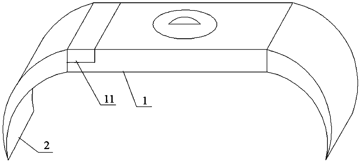
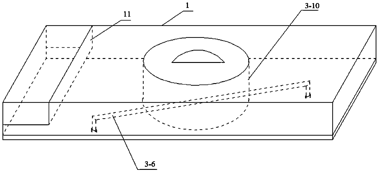
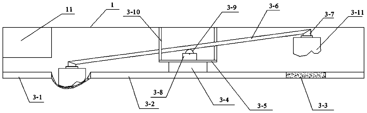
[0028] A gynecological uterus heating massage device, such as Figure 1-2 As shown, including the abdomen-contacting shell 1 and the waist belt 2 symmetrically installed on both sides of the abdomen-contacting shell 1, the top and side surfaces of the abdomen-contacting shell 1 surround the shape of a cuboid, and the top and side surfaces of the abdomen-contacting shell 1 Both are made of hard materials; the waist belt 2 is made of elastic cloth or ordinary cloth, one end of the two waist belts 2 are respectively fixed and bonded with the opposite sides of the abdomen contacting shell 1, and the other end of one waist belt 2 is fixed and glued. The other end of the other waist belt 2 is fixedly bonded or sewed with a velcro surface that can be detachably connected with the hook surface of the Velcro, so that the two waist belts 2 contact the shell 1 away from the abdomen. The bottom surface of the abdomen contacting shell 1 is composed of heating massage components, and a heat...

Embodiment 2

[0035] A gynecological uterus heating massage device, comprising an abdominal contact shell 1, a belt 2, a heating power supply cavity 11, a heating power supply, a heating massage assembly, and a point massage drive assembly. The structure and connection mode of the above components are basically the same as those of the first embodiment The same, the difference is:

[0036] The structure of heating massage components is as follows Figure 6-7 As shown, as follows: including cloth bag 4-1, circulating water pipe 4-2, circulating pump 4-3, water storage tank 4-4, water pipe guide channel 4-5, and water heating switch. The cloth bag 4-1 has a double-layer structure, the lower layer is disposed near the abdomen of the human body, and the upper layer is disposed close to the abdomen in contact with the upper surface of the casing 1. Preferably, the cloth bag 4-1 has a rectangular shape. The edges of the cloth bag 4-1 are respectively connected with the bottom edges of the four s...


PUM


Abstract

The invention belongs to the technical field of medical auxiliary instruments, and particularly relates to a gynecological uterus heating and massaging device. The device comprises an abdomen contactshell and waistbands symmetrically arranged on the two sides of the abdomen contact shell; the ends, away from the abdomen contact shell, of the two waistbands are detachably connected; the bottom surface of the abdomen contact shell is composed of a heating massage component; a heating power supply cavity is arranged on the inner wall of the abdomen contact shell; a heating power source is arranged in the heating power supply cavity; a point type massage driving component which protrudes downwards at a certain position and is arranged at the bottom of the heating massage component is arrangedin the abdomen contact shell. The uterus heating device is mild in massage mode, the massage position can be changed, and the comfort degree of a patient can be improved.

Description

technical field [0001] The invention belongs to the technical field of medical aids, and in particular relates to a gynecological uterus heating massage device. Background technique [0002] Uterine heating is an important means to treat irregular menstruation, dysmenorrhea, uterine fibroids and other uterine diseases. Uterine heating is divided into intrauterine heating and external heating to the uterus. Intrauterine heating means generally refers to heating the uterus with an instrument placed in the uterine cavity or the cervix. The heat source can directly contact the uterine wall and other parts. For example, heating the uterus can treat cervical cancer (locally advanced cervical cancer simultaneously releases, Phase II trial of chemotherapy and heating therapy, He Guoli et al., "Foreign Medicine. Obstetrics and Gynecology Volume", 2004-02), placing the uterine thermosphere in the uterine cavity can treat menorrhagia (the uterine thermosphere in the treatment of menst...

Claims


Application Information

Patent Timeline
IPC IPC(8): A61F7/00A61H23/02
CPCA61F7/00A61H23/02A61H23/006A61F2007/0022A61F2007/0054A61H2201/165A61H2205/083
Inventor 宋国英
Owner PINGDINGSHAN UNIVERSITY
Why Eureka
Try Eureka