Positioning frame device used for gynecological surgery

A technology for gynecological surgery and a rack device, which is applied in the field of body position rack devices for gynecological surgery, can solve problems such as inability to adjust the patient's position, unfavorable surgery, increase accident risks, etc., and achieve the effects of avoiding scratching hands and reducing use costs.

Inactive Publication Date: 2019-11-15
李菲
View PDF1 Cites 4 Cited by
  • Summary
  • Abstract
  • Description
  • Claims
  • Application Information

AI Technical Summary

Problems solved by technology

[0004] The purpose of the present invention is to provide a body position frame device for gynecological surgery, to solve the problem that the existing body position frame for gynecological surgery has a single function, and the patient may move around due to nervousness during the operation, which will affect the doctor's operation. There is no decompression structure on the body position frame, which makes the patient unable to release the tension, which is not conducive to the operation; the height of the leg support blocks on the existing gynecological operation body frame cannot be adjusted, and cannot be applied to patients of different heights. Patients of different heights need to replace different body position stand devices, which is costly; the position of the leg support blocks on the existing gynecological surgery position stand cannot be rotated, and the doctor cannot place the position of the patient's legs according to different situations, which increases the difficulty of the operation ; The existing gynecological surgery position frame cannot adjust the patient's position during the operation, and cannot adjust the patient's height position, and cannot be applied to doctors of different heights for surgical work, resulting in the comfort of the doctor's operation. Poor, unable to guarantee a perfect state, increasing the risk of accidents

Method used


Image

  • Positioning frame device used for gynecological surgery
  • Positioning frame device used for gynecological surgery
  • Positioning frame device used for gynecological surgery

Examples


Embodiment Construction

[0033] The technical solutions of the present invention will be clearly and completely described below in conjunction with the embodiments. Apparently, the described embodiments are only some of the embodiments of the present invention, not all of them. Based on the embodiments of the present invention, all other embodiments obtained by persons of ordinary skill in the art without creative efforts fall within the protection scope of the present invention.

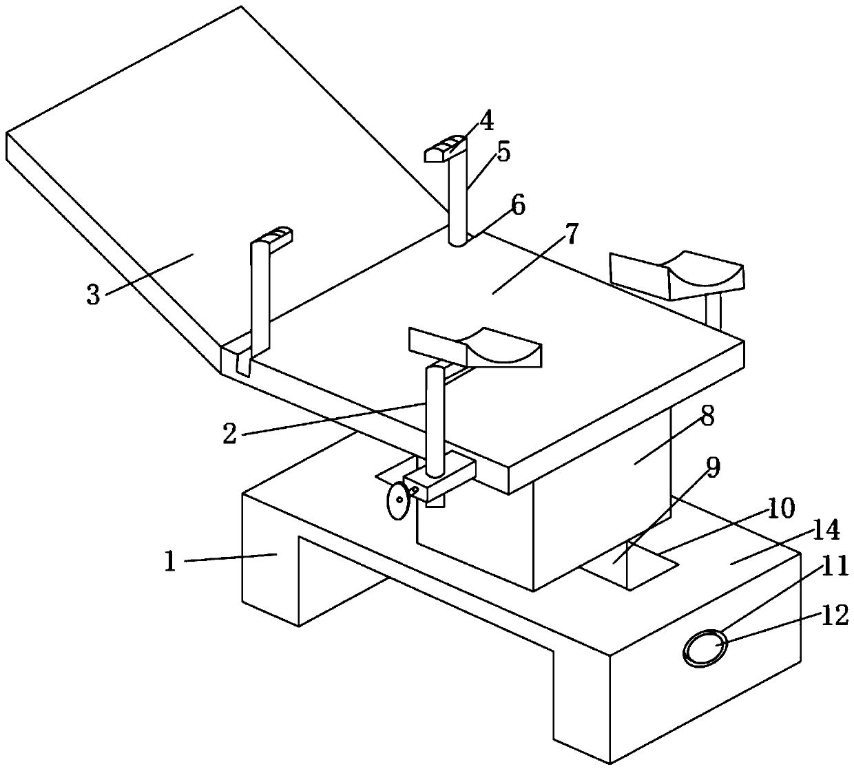
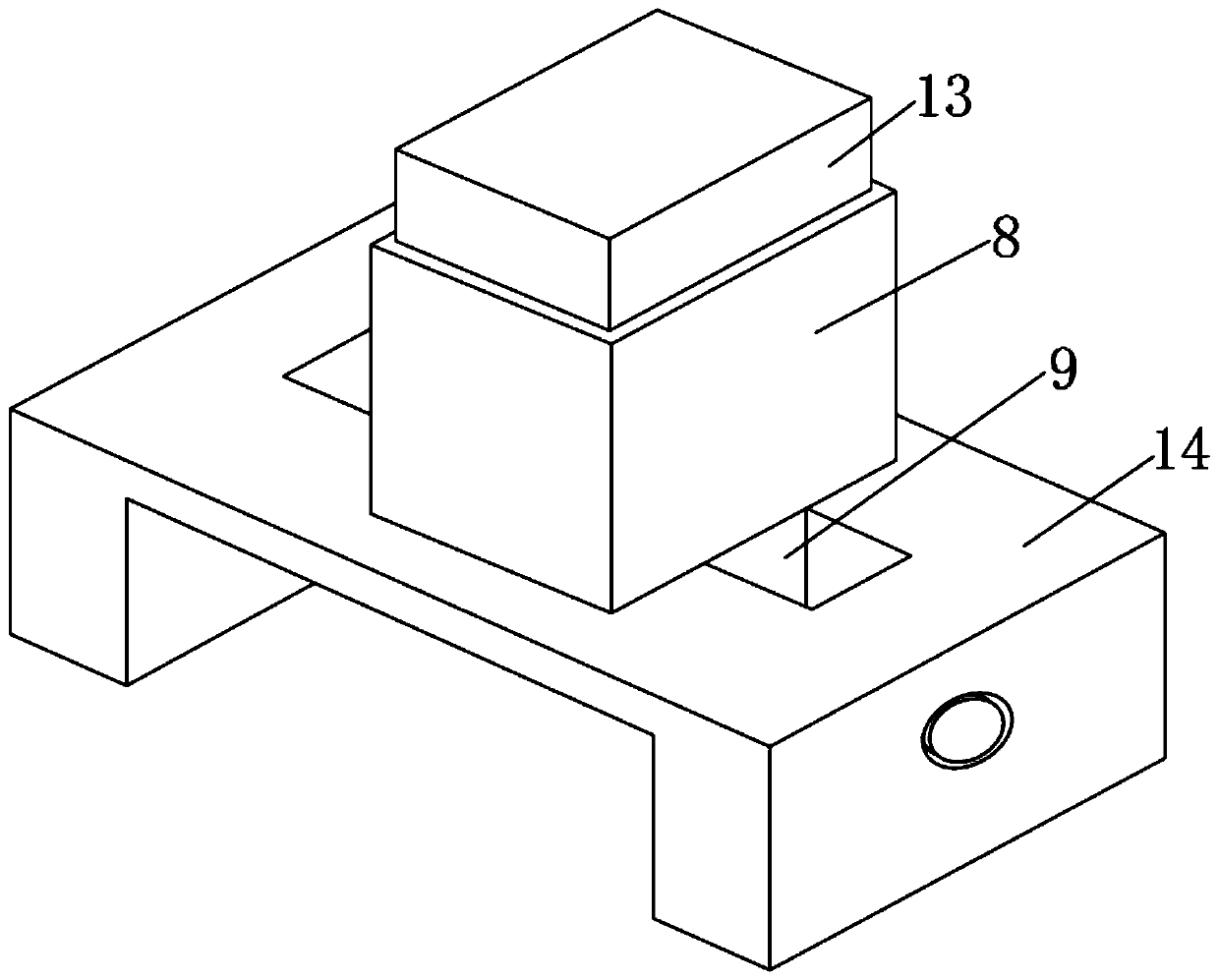
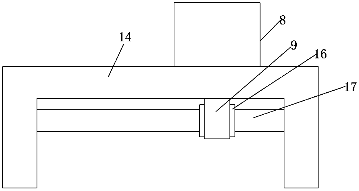
[0034] like Figure 1-7 As shown, a position frame device for gynecological surgery includes a fixed plate 1, a support device 2 and a horizontal plate 14, the two ends of the bottom of the horizontal plate 14 are respectively provided with a fixed plate 1, and the top of the horizontal plate 14 is provided with Hydraulic cylinder 8, the middle position of horizontal plate 14 is provided with chute 10, and the bottom of hydraulic cylinder 8 is provided with sliding block 9, and the top of sliding block 9 is fixedly connecte...


PUM


Abstract

The invention discloses a positioning frame device used for a gynecological surgery, which comprises fixing plates, a supporting device and a horizontal plate. The two ends of the bottom of the horizontal plate are respectively provided with fixing plates, the top of the horizontal plate is provided with a hydraulic cylinder, a sliding slot is formed in a middle portion of the horizontal plate, asliding block is disposed at the bottom of the hydraulic cylinder, a supporting plate is pulled to move up and down, so that a lifting rod moves in an inserted slot, when the lifting rod is moved to adesignated position, a rotating wheel is rotated, so that a fastening rod rotates, since one end of the fastening rod passes through the inside of a second nut seat and is screwed with the second nutseat, the fastening rod pushes a baffle plate to move in the direction of the lifting rod, the position of the lifting rod is fixed by pressing an anti-slip mat, the height of a leg support block canbe adjusted for patients of different heights, replacement of different positioning frame devices for the patients with different heights is not required, and the use cost is reduced.

Description

technical field [0001] The invention relates to the field of gynecological surgery equipment, in particular to a body position frame device for gynecological surgery. Background technique [0002] Existing posture frames for gynecological operations have a single function. During the operation, the patient may move agitated due to nervousness, which will affect the doctor’s operation. There is no decompression structure on the existing posture frames, which makes the patient unable to release the tension, which is not conducive to the operation. ; The height of the leg support blocks on the existing gynecological operation posture frame cannot be adjusted, and cannot be applied to patients of different heights. When encountering patients with different heights, different posture frame devices need to be replaced, and the use cost is high; the existing The position of the leg support blocks on the gynecological operation posture frame cannot be rotated, and the doctor cannot ...

Claims


Application Information

Patent Timeline
Patent Type & Authority Applications(China)
IPC IPC(8): A61G13/12A61G13/02A61G13/06
CPCA61G13/02A61G13/06A61G13/12A61G13/124A61G13/1245A61G13/129
Inventor 李菲李登平李慧
Owner 李菲
Why Eureka
Try Eureka