
Airway device, and laryngeal-branch combined lung separation system based on airway device

A separation system and airway technology, applied in bronchoscopes, medical devices, tracheal intubation, etc., can solve the problems of pollution, limited efficacy, and inability to deflate the catheter.

Active Publication Date: 2019-11-15
周星光
View PDF14 Cites 2 Cited by
  • Summary
  • Abstract
  • Description
  • Claims
  • Application Information

AI Technical Summary

Problems solved by technology

The tube is structurally simple and easy to place, but may have disadvantages
Some possible disadvantages include: 1) Because the right main bronchus is short and close to the tracheal bifurcation, when the single-lumen endobronchial catheter is placed on the right side, its balloon may block the opening of the right upper lobe bronchus, and effective ventilation is limited to the right middle In the lower lobe, this condition is usually not suitable for effective ventilation and oxygenation; 2) For the contralateral lung, that is, the diseased or operated lung, this type of catheter can neither deflate nor lack channels; 3) If the lung Insufflation or ventilation of the contralateral operative lung is required during surgery for surgical or anesthesia reasons and the catheter must be dialed back into the trachea, compromising isolation and causing contamination
However, this combined approach cannot avoid the limitations of bronchial occluders, namely limited efficacy and inability to establish access to the lung on the diseased side

Method used


Image

  • Airway device, and laryngeal-branch combined lung separation system based on airway device
  • Airway device, and laryngeal-branch combined lung separation system based on airway device
  • Airway device, and laryngeal-branch combined lung separation system based on airway device

Examples


Embodiment Construction

[0042] The drawings and description are not restrictive but illustrative in nature, the scope of the application being pointed out in the claims. While the embodiments are typical and preferred, the invention is not limited to these descriptions.

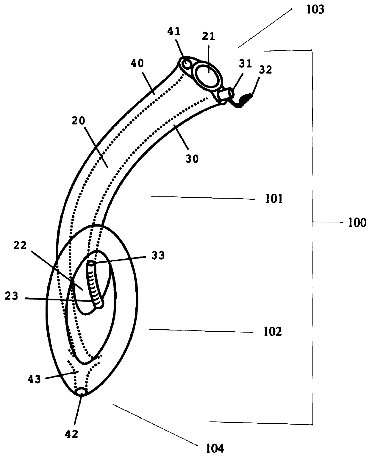
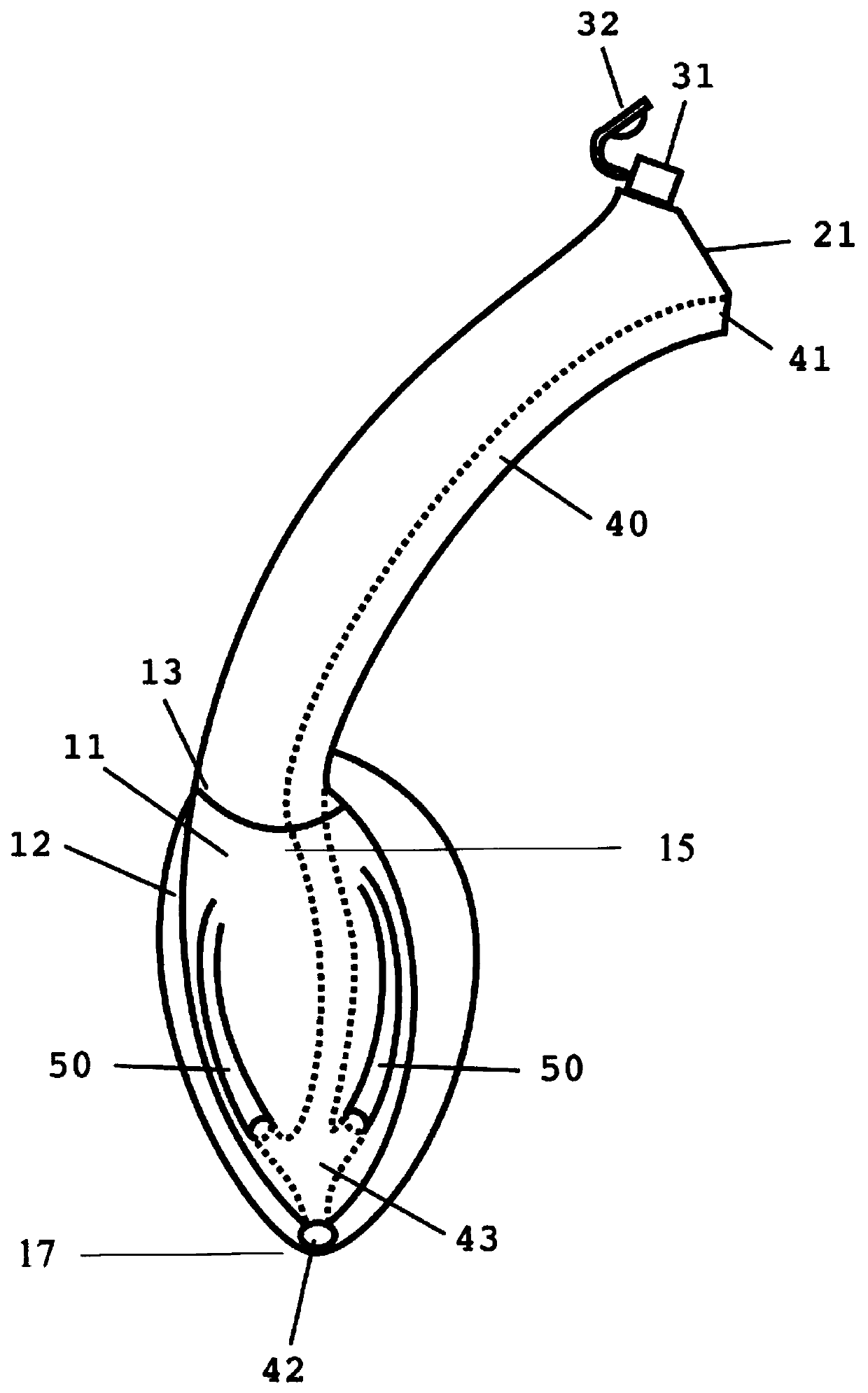
[0043] Figure 1A-B depicts an airway device 100 according to an embodiment of the present invention. The airway device 100 may be a multi-channel laryngeal mask which may comprise a mask body portion 102 and a channel portion 101; the channel portion 101 may extend from a proximal end 103 of the airway device 100 to a distal end of the mask body portion 102 104. The airway device 100 can be made of a disposable material, such as PVC or silicone, in different sizes to suit people of different sizes and shapes.

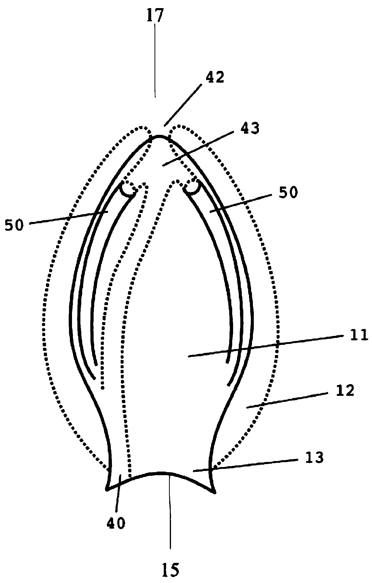
[0044] Such as Figure 1B with figure 2 As shown, the shell portion 102 is formed by a pear-shaped vaulted dome back panel 11 which may be surrounded by a membranous bladder 12 . The cover back 11 may have a circular d...


PUM


Abstract

The invention discloses an airway device, and a laryngeal-branch combined lung separation system based on the airway device. The system comprises: 1) a laryngeal mask type airway device, including a mask body portion defined at the distal end of the airway device, and a channel portion extending from the proximal end of the airway device to the cover portion, wherein the mask body portion can be positioned in the hypopharyngeal area of the patient to cover and seal the patient's glottis; 2) a bronchial isolation catheter used in combination with a laryngeal mask airway device. The channel portion of the laryngeal mask type airway device may include first and second channels, wherein the second channel may be inclinedly merged with the first channel near an opening near the first channel. In an exemplary embodiment, the third channel may form a gastro-pharyngeal combined channel. The bronchial isolation catheter is constructed and sized to be inserted into the first opening of the airway channel and through the second opening of the airway channel. When the laryngeal mask is located in the hypopharyngeal area of the patient, the laryngeal mask enters the left or right bronchus of the patient through the trachea.

Description

[0001] related application [0002] This application claims priority to U.S. Provisional Application No. 62 / 670,418, filed May 11, 2018, the disclosure of which is incorporated herein by reference in its entirety. technical field [0003] The content of the present document relates to a medical device consisting of an airway device or system. In some cases, the present invention relates to the ability to both isolate and deflate the operated / affected lung during surgery and procedures requiring one-lung ventilation or one-lung anesthesia in normal or difficult airway situations. Devices for ventilation and manipulation. Background technique [0004] One-lung ventilation Lung isolation is a medical and anesthesia technique that can be used in surgical procedures such as thoracotomy, thoracoscopy or video-assisted thoracoscopic surgery, and in conditions such as alveolar proteinosis. One-lung ventilation can be achieved by occluding and isolating one lung while selectively v...

Claims


Application Information

Patent Timeline
IPC IPC(8): A61M16/00A61M16/01A61M16/04
CPCA61M16/00A61M16/01A61M16/0404A61M16/0463A61M2205/583A61M16/0409A61M16/0415A61M16/085A61M16/0833A61B1/2676A61M16/04A61M16/0434A61M16/0486A61M16/0445A61M16/0057A61M16/0406A61M16/0816A61M2205/584
Inventor 周星光
Owner 周星光
Learn More