
Pneumatic lifting platform

A technology of pneumatic lifting and lifting platform, applied in the direction of grinding workpiece support, grinding frame, grinding bed, etc., can solve the problems of straightness error, uneven grinding uneven, track damage, etc., to achieve strong adaptability Effect

Pending Publication Date: 2019-11-15
WUXI HUALIAN SCI & TECH GROUP
View PDF0 Cites 0 Cited by
  • Summary
  • Abstract
  • Description
  • Claims
  • Application Information

AI Technical Summary

Problems solved by technology

[0002] The lifting device used in the traditional grinding machine is that the motor drives the screw pair to rotate to lift the platform. Since the screw rod will have a straightness error when installed, the screw rod will wear out after a long time, which will cause the grinding machine on the lifting platform to move incorrectly. Even, it will damage the track, the grinding is uneven and uneven, and the grinding effect is not good

Method used


Image

  • Pneumatic lifting platform
  • Pneumatic lifting platform

Examples


Embodiment Construction

[0017] The present invention will be further described below in conjunction with specific drawings.

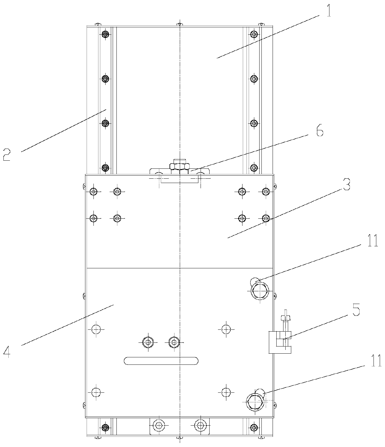
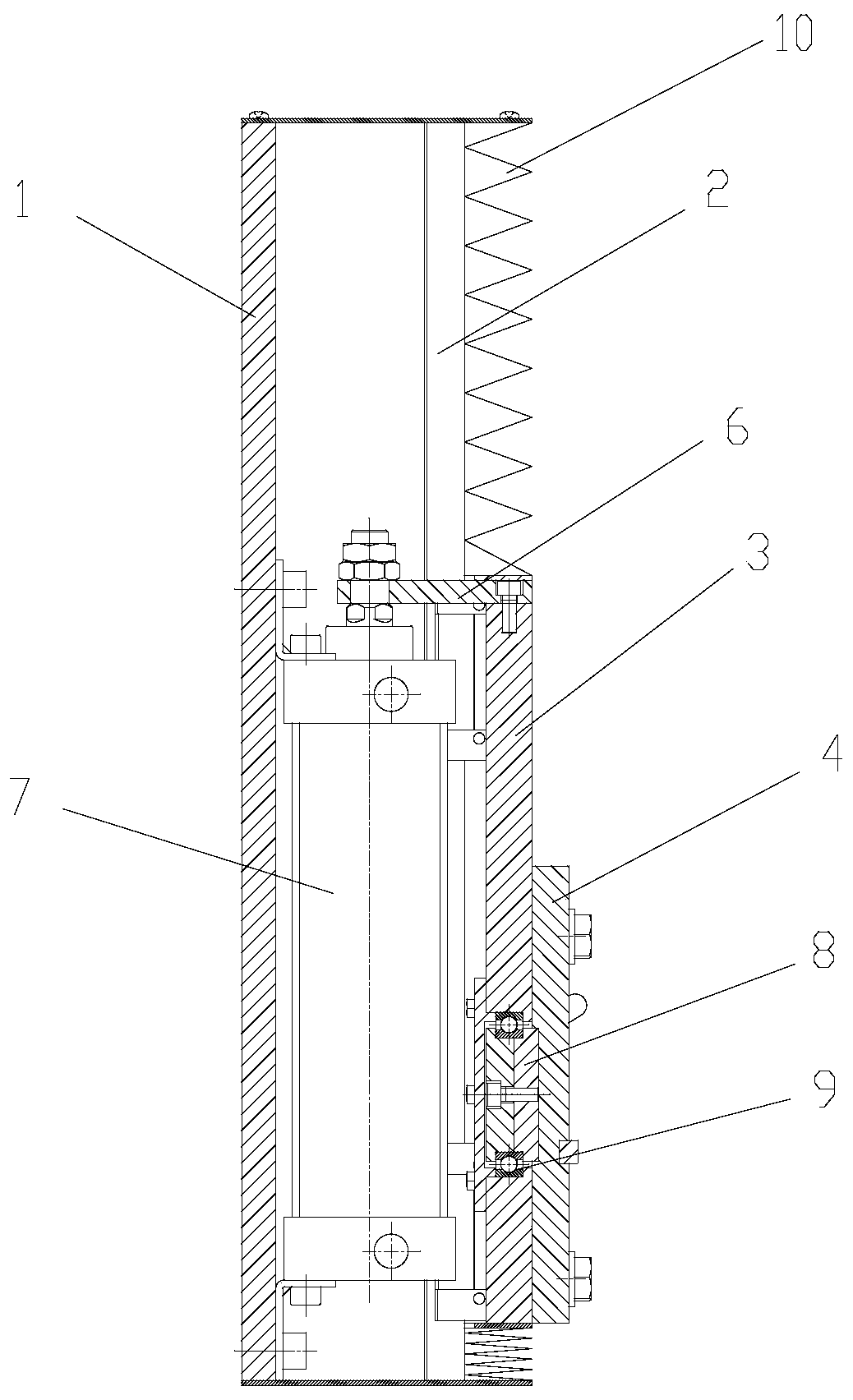
[0018] Such as figure 1 and figure 2 As shown, a pneumatic lifting platform includes a base 1, a linear guide rail 2, a lifting platform 3, a rotating platform 4, a connecting plate 6, a cylinder 7 and a positioning shaft 8, and the linear guide rails 2 are respectively arranged on both sides of the base 1, and the The lifting platform 3 is connected with the linear guide rail 2; the cylinder 7 is fixedly installed on the base 1, and the cylinder 7 is fixed on the lifting platform 3 through the connecting plate 6; the rotating platform 4 is fixed on the positioning shaft 8.

[0019] Described positioning shaft 8 is supported by rolling bearing 9, and rolling bearing 9 is contained in the lifting platform 3, uses end plate and hexagonal bolt to lock.

[0020] An adjustment and rotation device 5 is provided on the pneumatic lifting platform; the adjustment and rotation device...


PUM


Abstract

The invention relates to a pneumatic lifting platform which comprises a base, linear guide rails, a lifting platform, a rotating platform, a connecting plate, an air cylinder and a positioning shaft.The linear guide rails are respectively arranged on two sides of the base, and the lifting platform is connected with the linear guide rails; the base is fixedly provided with the air cylinder, and the air cylinder is fixed on the lifting platform through the connecting plate; and the rotary platform is fixed on the positioning shaft. According to the pneumatic lifting platform, a poor grinding effect caused by abrasion of a lead screw can be avoided, a grinding head is pushed by the air cylinder, so that the position error compensation function of the grinding head is realized, and the adaptability to the shape of a workpiece is higher.

Description

technical field [0001] The invention relates to a pneumatic lifting platform, which belongs to the technical field of mechanical processing equipment. Background technique [0002] The lifting device used in the traditional grinding machine is that the motor drives the screw pair to rotate to lift the platform. Since the screw rod will have a straightness error when installed, the screw rod will wear out after a long time, which will cause the grinding machine on the lifting platform to move incorrectly. If it is uniform, it will damage the track, if the grinding is uneven and uneven, the grinding effect will not be good. Contents of the invention [0003] The object of the present invention is to overcome the deficiencies in the prior art, and provide a pneumatic lifting platform, which can be lifted and lowered stably without the problems of the traditional grinding machine lifting device. [0004] According to the technical solution provided by the present invention: a...

Claims


Application Information

Patent Timeline
Patent Type & Authority Applications(China)
IPC IPC(8): B24B41/06B24B41/02
CPCB24B41/06B24B41/02
Inventor 吴仲贤吴清陆松茂
Owner WUXI HUALIAN SCI & TECH GROUP
Learn More