Shield machine cutter head with variable cutter spacing

A technology of shield machine and cutter head, which is used in mining equipment, earth-moving drilling, tunnels, etc., can solve the problem of invariable distance between hob cutters, and achieve the effect of reducing construction difficulty, speeding up construction progress, and improving adaptability

Active Publication Date: 2019-11-15
CHINA RAILWAY ENGINEERING EQUIPMENT GROUP CO LTD
View PDF11 Cites 5 Cited by
  • Summary
  • Abstract
  • Description
  • Claims
  • Application Information

AI Technical Summary

Problems solved by technology

[0005] Aiming at the deficiencies in the above-mentioned background technology, the present invention proposes a shield machine cutterhead with variable cutter spacing, which solves the technical problem that the hob cutter spacing on the existing shield machine cutterhead is not variable

Method used


Image

  • Shield machine cutter head with variable cutter spacing
  • Shield machine cutter head with variable cutter spacing
  • Shield machine cutter head with variable cutter spacing

Examples


Embodiment 1

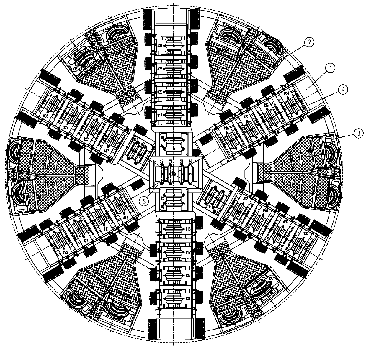
[0022] Embodiment 1, a shield machine cutterhead with variable cutter spacing, such as figure 1 As shown, including the main beam 1 of the cutter head, the hob assembly 4 is adjustable inside the main beam 1 of the cutter head, and the compression bolt groups for fixing the hob assembly 4 are arranged at intervals on the main beam 1 of the cutter head. The set of tightening bolts enables the adjustment of the spacing between the hob assemblies, ie the spacing between adjacent hobs.

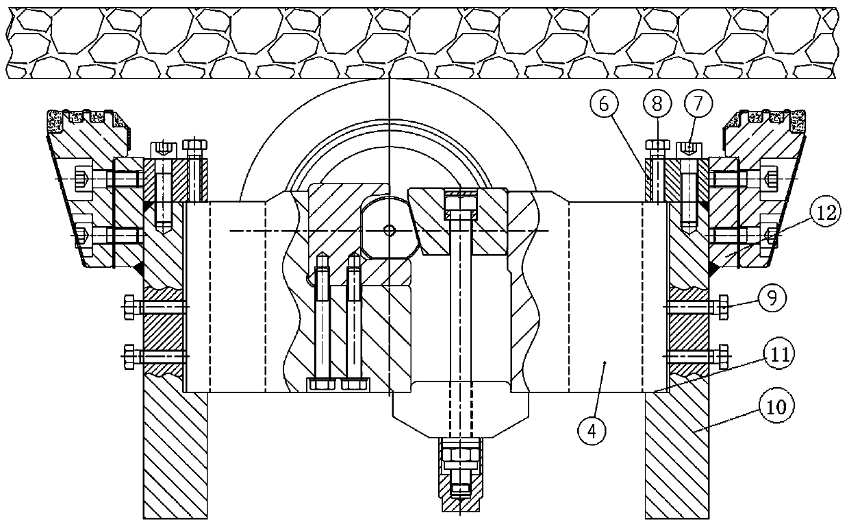
[0023] Such as image 3 As shown, the cutterhead main beam 1 includes two symmetrically arranged fixed beams 10, and the opposite inner sides of the two fixed beams 10 are provided with shoulders 11 arranged along the radial direction of the shield machine cutterhead, and the hob is assembled The body 4 is fixedly arranged in the two shoulders 11, which not only facilitates the assembly of the hob assembly 4 and the main beam 1 of the cutter head, but also facilitates the adjustment of the positi...

Embodiment 2

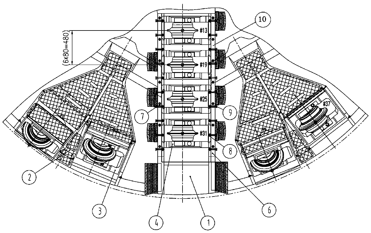
[0029] Embodiment 2, a shield machine cutterhead with variable cutter spacing, such as figure 2As shown, the pressing block 6 is arranged along the radial direction of the main beam of the cutter head 1 and is in the shape of a long strip, so that no matter how the position of the tool box assembly 4 is adjusted, it will be crimped under the pressing block 4 of the tool box. The structure is simplified, and it is convenient to adjust the position of the hob assembly 4 and fix it again.

[0030] The structure of this embodiment is the same as that of Embodiment 1.

Embodiment 3

[0031] Embodiment 3, a shield machine cutterhead with variable cutter spacing, the distance between the pressing bolts 9 adjacent to the side of the cutter box is less than two times the width of the hob assembly 4 along the radial direction of the shield machine cutterhead One-third, it can ensure that no matter how the position of the hob assembly 4 is adjusted, at least two groups of knife box side compression bolts 9 can be crimped on the side of a hob assembly 4.

[0032] The distance between the second pressing bolts 8 adjacent to the front of the cutter box is less than half of the width of the hob assembly 4 along the radial direction of the cutter head of the shield machine. This can ensure that no matter how the position of the hob assembly 4 is adjusted, at least two sets of second compression bolts 8 on the front of the knife box are crimped on the front of one hob assembly 4 .

[0033] The structure of this embodiment is the same as Embodiment 1 or 2.


PUM


Abstract

The invention discloses a shield machine cutter head with variable cutter spacing, and solves the technical problem that the hob spacing on the existing shield machine cutter head is not variable. Theshield machine cutter head comprises a cutter main beam, wherein a hob assembly is arranged in the cutter main beam, and a compression bolt set for fixing the hob assembly is arranged on the cutter main beam at interval. The invention realizes the function of adjusting the cutter spacing of the hob correspondingly according to the construction geological change through changing the fixing mannerof the hob assembly, and achieves the efficient matching of the cutter spacing arrangement and the construction geology, and can ensure the rock-breaking efficiency of the hob in different geologies,reduces the construction difficulty, speeds up the construction progress, prolongs the cutter life, reduces the number of inspections and cutter change; meanwhile, the construction cost is reduced, the adaptability of the shield cutter is improved, and the long distance, efficient and reliable tunneling of the shield machine is ensured.

Description

technical field [0001] The invention relates to the technical field of shield machines, in particular to a shield machine cutterhead with variable cutter spacing. Background technique [0002] With the active advancement of national water conservancy and hydropower projects, subway tunnel projects, and underground space development projects, as well as the gradual maturity of research and development and manufacturing capabilities of shield machines and construction technologies, shield construction has been widely used due to its advantages in safety, efficiency, and economy. , in which the disc-shaped hob is the main rock-breaking tool of the shield machine during the excavation process, and its rock-breaking effect will directly affect the efficiency and cost of underground engineering construction. [0003] Existing shield machines for tunneling mainly rely on disc-shaped hobs to squeeze rocks to achieve the purpose of breaking rock masses, and what they mainly overcome ...

Claims


Application Information

Patent Timeline
Patent Type & Authority Applications(China)
IPC IPC(8): E21D9/08
CPCE21D9/08E21D9/0874
Inventor 张家年于金达黄士广张世伟喻中孝宋春晓任涪伟
Owner CHINA RAILWAY ENGINEERING EQUIPMENT GROUP CO LTD
Why Eureka
Try Eureka