Eureka AIR delivers breakthrough ideas for toughest innovation challenges, trusted by R&D personnel around the world.

An easy-to-move oil-free air compressor

A technology of air compressors and driving machines, which is applied in the direction of machines/engines, mechanical equipment, liquid variable capacity machinery, etc. It can solve the problems of cylinder pressure, damage to mechanical parts, and failure to realize pressure relief, etc., to prolong the service life Effect

Active Publication Date: 2020-12-15
佛山市威盈加科技有限公司
View PDF6 Cites 0 Cited by
  • Summary
  • Abstract
  • Description
  • Claims
  • Application Information

AI Technical Summary

Problems solved by technology

[0004] Aiming at the deficiencies in the prior art, the purpose of the present invention is to provide an oil-free air compressor that is easy to move, so as to solve the problem of preventing the compressor from starting under pressure after the oil-free air compressor in the prior art is shut down. When starting the machine, it is necessary to pull the air release valve to exhaust, which is troublesome, and the staff often forget to release the pressure before starting the machine. At the same time, the traditional pressure relief method cannot achieve a real and complete pressure relief, resulting in the presence of residual gas in the cylinder. Such starting will cause the load of the motor to be several times higher than normal, which will easily cause damage to the motor, and will cause the moving parts to suffer sudden force or uneven force, which will damage or reduce the life of the mechanical parts. Defects such as rod or piston bending

Method used


Image

  • An easy-to-move oil-free air compressor
  • An easy-to-move oil-free air compressor
  • An easy-to-move oil-free air compressor

Examples


Embodiment Construction

[0024] In order to make the technical means, creative features, goals and effects achieved by the present invention easy to understand, the present invention will be further described below in conjunction with specific embodiments.

[0025] Such as Figure 1-Figure 5 As shown, the present invention provides a kind of technical scheme of the oil-free air compressor that is convenient to move:

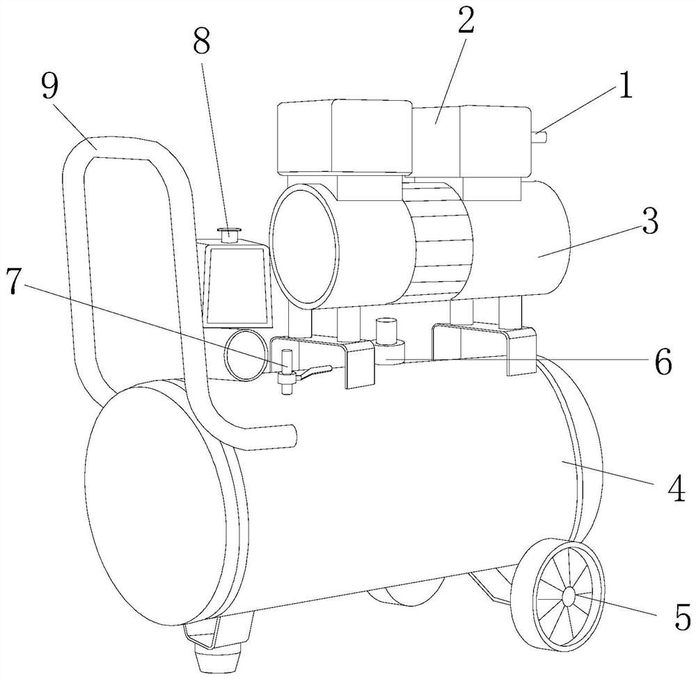
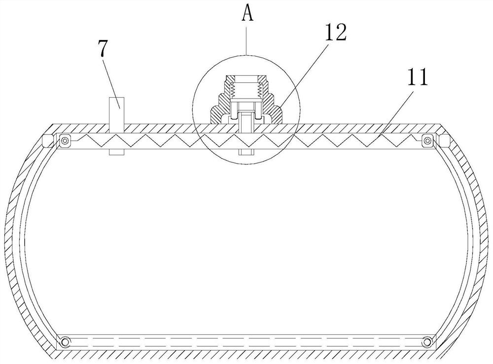
[0026] An oil-free air compressor that is easy to move, its structure includes a suction nozzle 1, a machine head 2, a driving machine 3, a compression cylinder 4, a moving roller 5, an air cleaning and pressure relief device 6, an air outlet valve 7, a switch 8, Push-pull handle 9, the suction nozzle 1 is arranged on the side of the machine head 2 and connected through it, the driving machine 3 is arranged above the compression cylinder 4 and connected with the machine head 2, and the moving roller 5 is arranged on the compression cylinder 4 At the bottom four ends, the air-cleaning an...


PUM


Abstract

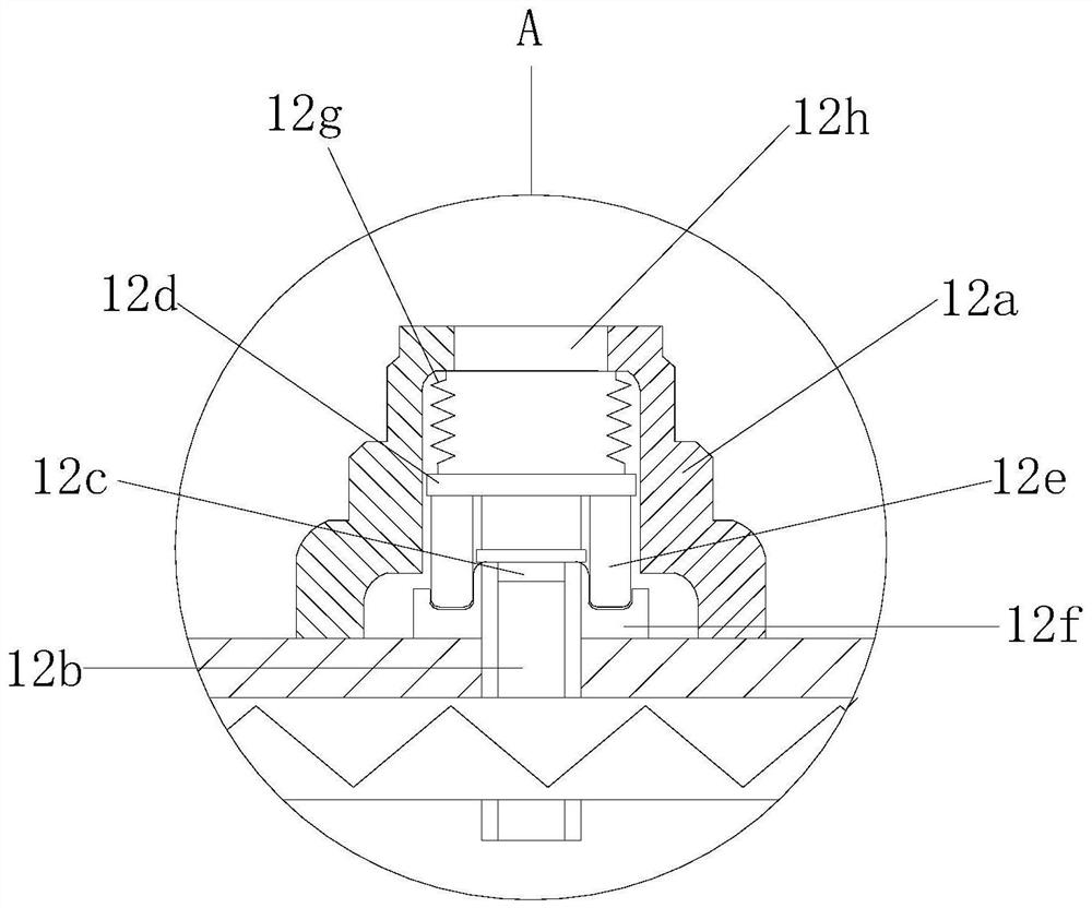
The invention discloses an oil-free air compressor capable of being easy to move, and the oil-free air compressor structurally comprises a suction nozzle, a machine head, a driving machine, a compression air cylinder, a movable roller, an air purge and pressure relief device, a gas outlet valve, a switch and a push-pull handle. The suction nozzle is arranged on the side of the machine head and iscommunicated with the machine head, the driving machine is arranged on the top of the compression air cylinder and is connected with the machine head, and the moving roller is arranged on the bottom four ends of the compression air cylinder. According to an opposite air purge mechanism which is arranged on the compression air cylinder, two purge push plates are used to slide from both sides of thecompression air cylinder to the middle of the compression air cylinder oppositely and the remaining air is concentrated in the middle position of the compression air cylinder when the compressor is powered off; and meanwhile, according to an electromagnetic pressure release mechanism which is arranged in the middle of the compression air cylinder, the electromagnetic magnetic loss can open the pressure relief valve, and the electromagnetic pressure relief mechanism and the opposite air cleaning mechanism can cooperate to clear all the air, prevent the equipment from starting with pressure, ensure the motor load is normal, protect the motor and mechanical parts, and prolongs the service life.

Description

technical field [0001] The invention relates to the field of oil-free air compressors, more precisely, an oil-free air compressor that is easy to move. Background technique [0002] The full name of the oil-free air compressor is the oil-free air compressor, which is the main body of the air source device. It is a device that converts the mechanical energy of the prime mover (usually a motor) into gas pressure energy, and is a pressure generating device for compressed air. But still there is following defect in the oil-free air compressor that is convenient to move of prior art: [0003] After the oil-free air compressor is powered off and shut down, in order to prevent the compressor from starting under pressure, it is necessary to pull the air release valve to exhaust when starting up again, which is troublesome, and the staff often forget to release the pressure before starting up. The traditional pressure relief method cannot achieve a truly complete pressure relief. Th...

Claims


Application Information

Patent Timeline
Patent Type & Authority Patents(China)
IPC IPC(8): F04B37/12F04B35/04F04B39/10F04B39/00
CPCF04B35/04F04B37/12F04B39/00F04B39/10
Inventor 陈志骋
Owner 佛山市威盈加科技有限公司
Why Eureka
Eureka Blog
Learn More