
Fingerprint module detecting device and fingerprint module detecting method

A fingerprint module and detection device technology, which is applied in the field of fingerprint identification, can solve problems such as outflow of defective products, wrong matching of test fixtures and fingerprint modules, batch defective products, etc., to avoid matching mistakes and point detection test fixtures , the effect of improving work efficiency

Inactive Publication Date: 2019-11-15
昆山丘钛生物识别科技有限公司
View PDF7 Cites 0 Cited by
  • Summary
  • Abstract
  • Description
  • Claims
  • Application Information

AI Technical Summary

Problems solved by technology

However, due to different specifications, different test fixtures are required for testing fingerprint modules of different models. At present, the test fixtures are generally tested manually, and it is very easy to match the test fixtures and fingerprint modules incorrectly, resulting in Wrong test fixtures test out defective products and flow out to the client, resulting in batches of defective products

Method used


Image

  • Fingerprint module detecting device and fingerprint module detecting method
  • Fingerprint module detecting device and fingerprint module detecting method
  • Fingerprint module detecting device and fingerprint module detecting method

Examples


no. 1 example

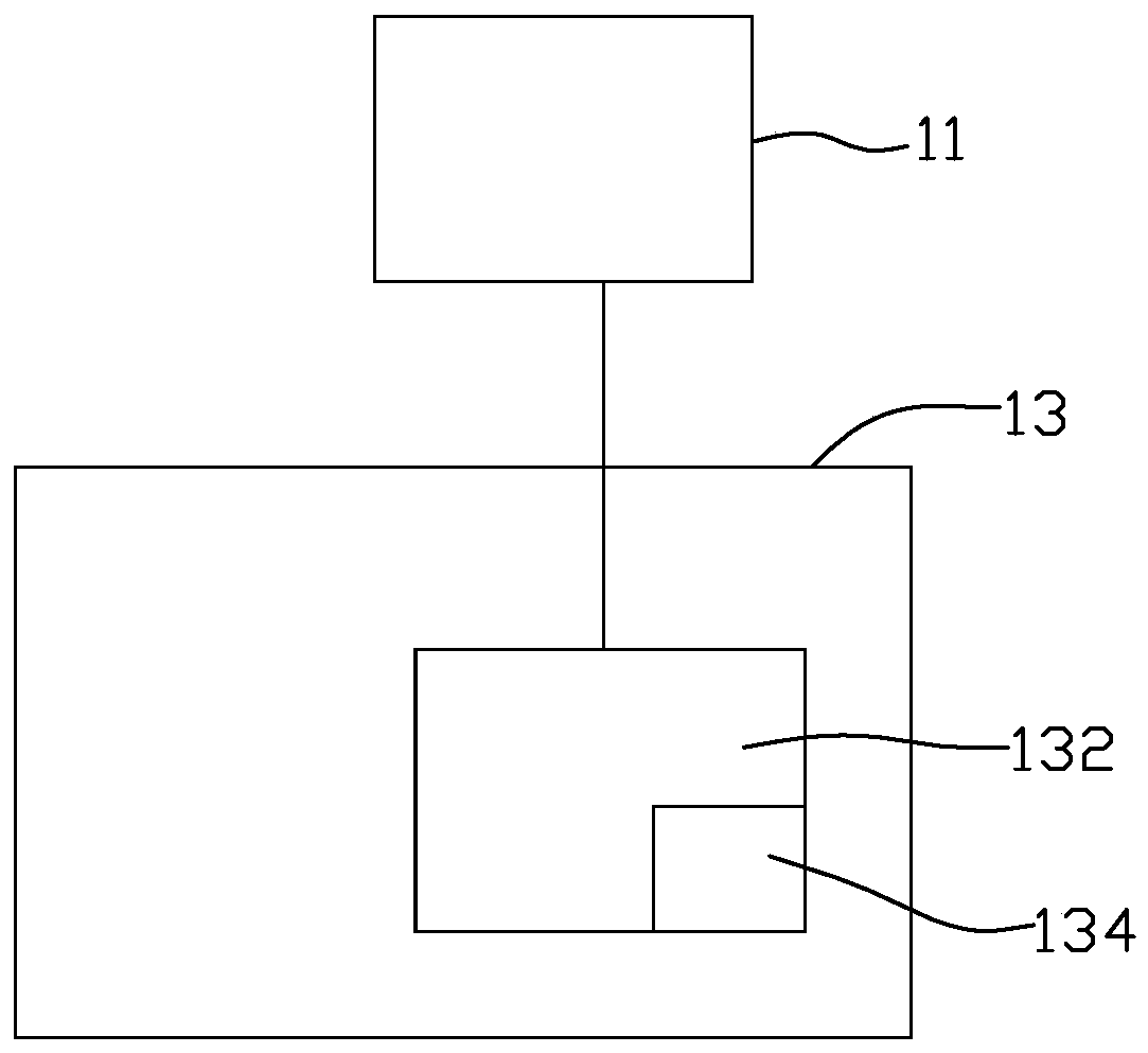
[0022] Please refer to figure 1 , the fingerprint module detection device provided in the first embodiment of the present invention includes a test machine 11 and a test fixture 13 . The test fixture 13 includes a test main board 132 . The test main board 132 is provided with a model circuit 134 . The model name of the fingerprint module that the test fixture 13 can test is pre-stored on the model circuit 134 . The test mainboard 132 is signal-connected to the test machine 11 , and the model circuit 134 is electrically connected to the test mainboard 132 .

[0023] The testing machine 11 can be a computer, such as an industrial computer, which has pre-stored testing software for testing the fingerprint module. The testing machine 11 is also used to read the model name pre-stored in the model circuit 134 .

[0024] The test fixture 13 is also used to carry the fingerprint module, and the electrical connection terminal of the fingerprint module is electrically connected to the...

no. 2 example

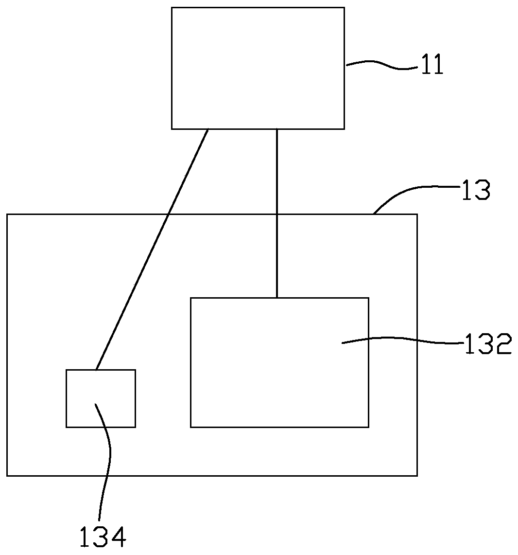
[0029] Please refer to figure 2 The fingerprint module detection device of the second embodiment of the present invention includes a test machine 11 and a test fixture 13, the structure of the fingerprint module detection device of the second embodiment is the same as the structure of the fingerprint module detection device of the first embodiment Similar, the difference is that in the second embodiment, the model circuit 134 is directly disposed on the test fixture 13 instead of the test main board 132 , and the model circuit 134 is directly connected to the test machine 11 for signals. The rest of the structure is the same as that of the first embodiment, and will not be repeated here.

no. 3 example

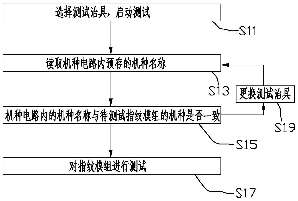
[0031] Please refer to image 3 The fingerprint module detection method of the third embodiment of the present invention uses the fingerprint module detection device of the first embodiment or the second embodiment to detect, and the fingerprint module detection method includes the following steps:


PUM


Abstract

The invention discloses a fingerprint module detecting device and a fingerprint module detecting method. The fingerprint module detecting device comprises a test fixture comprising a test main board and a model circuit. A model name of the fingerprint module detectable by the test fixture is pre-stored on the model circuit. In the fingerprint module detecting device and the fingerprint module detecting method, the model circuit can identify the model of the fingerprint module detectable by the test fixture, so that manual spot inspection for the test fixture can be avoided, thereby avoiding mismatch between the test fixture and the fingerprint module on the one hand and improving working efficiency on the other hand.

Description

technical field [0001] The invention relates to the technical field of fingerprint identification, in particular to a fingerprint module detection device and a fingerprint module detection method. Background technique [0002] With the rapid development of the electronics industry, fingerprint recognition technology is widely used. Not only can fingerprint recognition technology be seen in access control and attendance systems, but there are more fingerprint recognition applications on the market: such as laptops, mobile phones, cars , bank payment, etc. At present, fingerprint recognition technologies mainly include capacitive fingerprint recognition, optical fingerprint recognition and ultrasonic fingerprint recognition. [0003] For different electronic products, the specifications of the required fingerprint modules will also be different, resulting in different models, but the appearances of the fingerprint modules of different models are almost the same. However, due...

Claims


Application Information

Patent Timeline
Patent Type & Authority Applications(China)
IPC IPC(8): G01R31/00
CPCG01R31/00
Inventor 陈正伟王建陈蒙
Owner 昆山丘钛生物识别科技有限公司
Learn More