Cutting chip identification method for bending unit

A bending unit, bending tool technology, applied in the direction of using optical devices, optical device exploration, safety equipment, etc.

Pending Publication Date: 2019-11-15
TRUMPF MASCHEN AUSTRIA
View PDF8 Cites 0 Cited by
  • Summary
  • Abstract
  • Description
  • Claims
  • Application Information

AI Technical Summary

Problems solved by technology

Such vision systems are not adequately suited for implementation in the manufacturing process due to changing lighting conditions, possibly inappropriate surface properties due to residual oil or dirt, and changing sheet part geometries, for example

Method used


Image

  • Cutting chip identification method for bending unit
  • Cutting chip identification method for bending unit
  • Cutting chip identification method for bending unit

Examples


Embodiment Construction

[0056] First of all, it should be ensured that in the differently described embodiments, the same parts have the same reference signs or the same component designations, and that the disclosure content contained in the entire description can be transferred reasonably to the components with the same reference signs or the same component names. same parts. The selected position descriptions in the description, such as for example top, bottom, side, etc., refer to the currently described and shown figures and in the event of a position change, these position descriptions can be appropriately transferred to the new position.

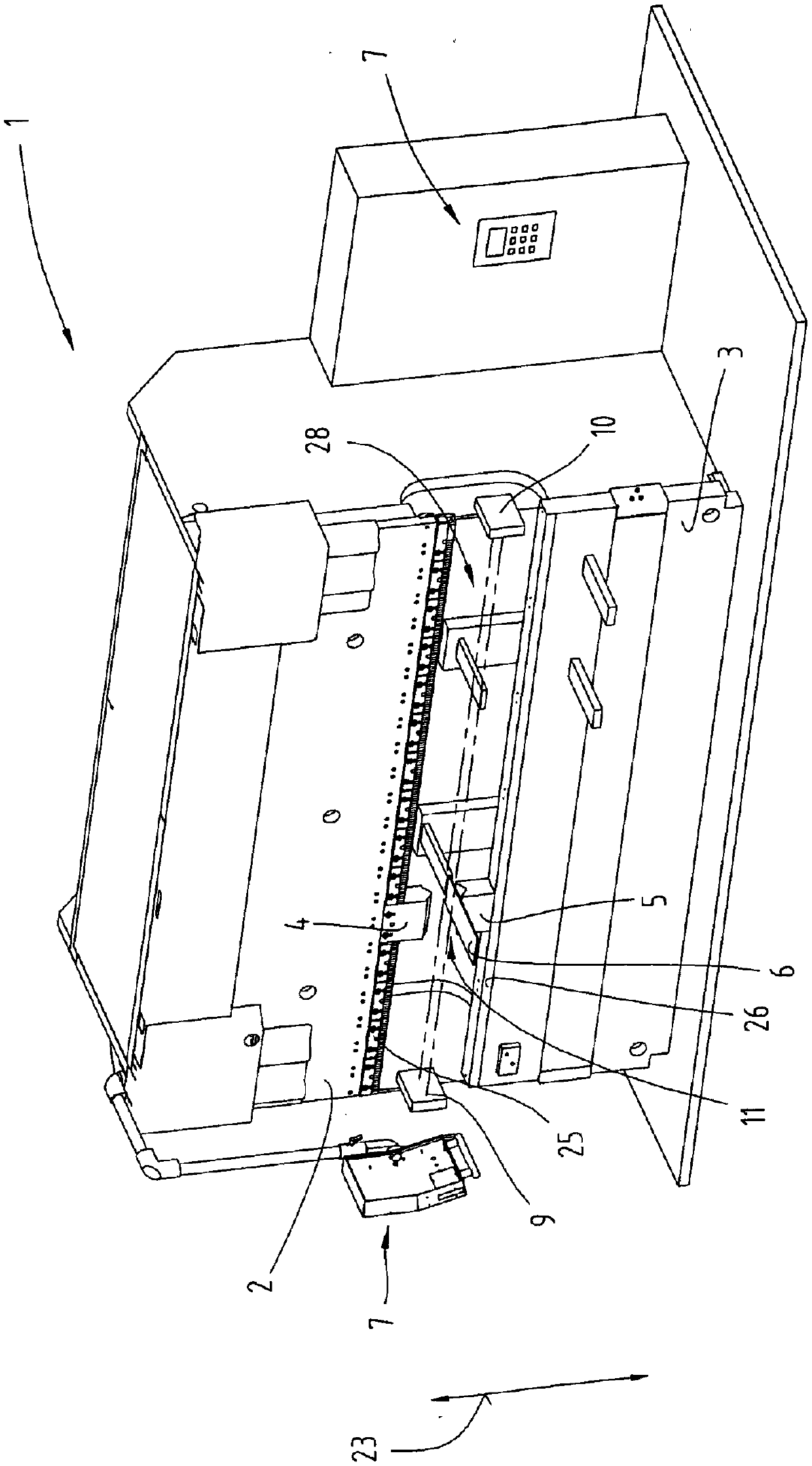
[0057] exist figure 1 A bending unit 1 is schematically shown in , which can be used in the method according to the invention. The bending unit 1 has a horizontal pressure beam 2 which is designed to be reciprocated in a direction of movement 23 by a drive unit not shown in detail. Upper tool 4 can be directly arranged on the pressure beam 2, or as figure...


PUM


Abstract

The invention relates to a method for detecting foreign matters, namely a waste material especially a cutting or stamping waste material, between a bending tool and a board piece to be molded. The method comprises the following steps that the bending unit which comprises an upper tool, a lower tool, an equipment controller, at least one light source and at least one light sensor for detecting theforeign matters is provided; in an opening position of the bending unit, at least one board piece is provided in a pre-prescribed position between the upper and lower tools; and the foreign matters between the bending tool and the board piece are detected by using the light source and light sensor to measure the contour of the lower tool between the light source and the light sensor, comparing thecontour of the lower tool with a pre-prescribed reference contour and/or a theoretical contour in the equipment controller, start molding of the board piece when the contours are consistent, or interrupting or ending the method when there is a deviation therebetween.

Description

technical field [0001] The invention relates to a method for detecting foreign objects, in particular cutting or punching waste, between at least one bending tool and a sheet metal part to be formed using at least one light source and at least one light sensor. Background technique [0002] When processing laser-processed, punched or also cut sheet metal, it often happens that foreign bodies in the form of cutting or punching waste settle on the sheet metal. This foreign matter is also known as cutting or stamping debris. Due to the use of oil, said residues or foreign matter sometimes adhere very strongly to the board. [0003] For further processing of the sheet metal, such as deep drawing, pressing or bending, such foreign bodies, such as for example cutting or punching chips, but also loose cutting or punching burrs can cause damage to the tool. In addition, such foreign matter adhering to the sheet may detach from the sheet and be transferred to the tool. If the fore...

Claims


Application Information

Patent Timeline
Patent Type & Authority Applications(China)
IPC IPC(8): G01V8/10G01B11/24
CPCG01V8/10G01B11/24B21D5/02B21D5/004B21D55/00F16P3/144
Inventor A·哈夫纳张楚帆
Owner TRUMPF MASCHEN AUSTRIA
Why Eureka
Try Eureka