Diagnosis method and system for industrial control device

A technology for industrial control equipment and diagnostic systems, applied in general control systems, control/regulation systems, testing/monitoring control systems, etc., can solve problems such as poor experience, inability to remotely diagnose old equipment, and inability to provide industrial control equipment, etc. Achieve the effect of improving work efficiency and user experience, and saving maintenance costs

Inactive Publication Date: 2019-11-15
深圳市智微智能软件开发有限公司
View PDF5 Cites 1 Cited by
  • Summary
  • Abstract
  • Description
  • Claims
  • Application Information

AI Technical Summary

Problems solved by technology

[0004] The purpose of the present invention is to provide a diagnostic method and system for industrial control equipment, aiming to solve the problem that users cannot remotely

Method used


Image

  • Diagnosis method and system for industrial control device
  • Diagnosis method and system for industrial control device

Examples


Embodiment 1

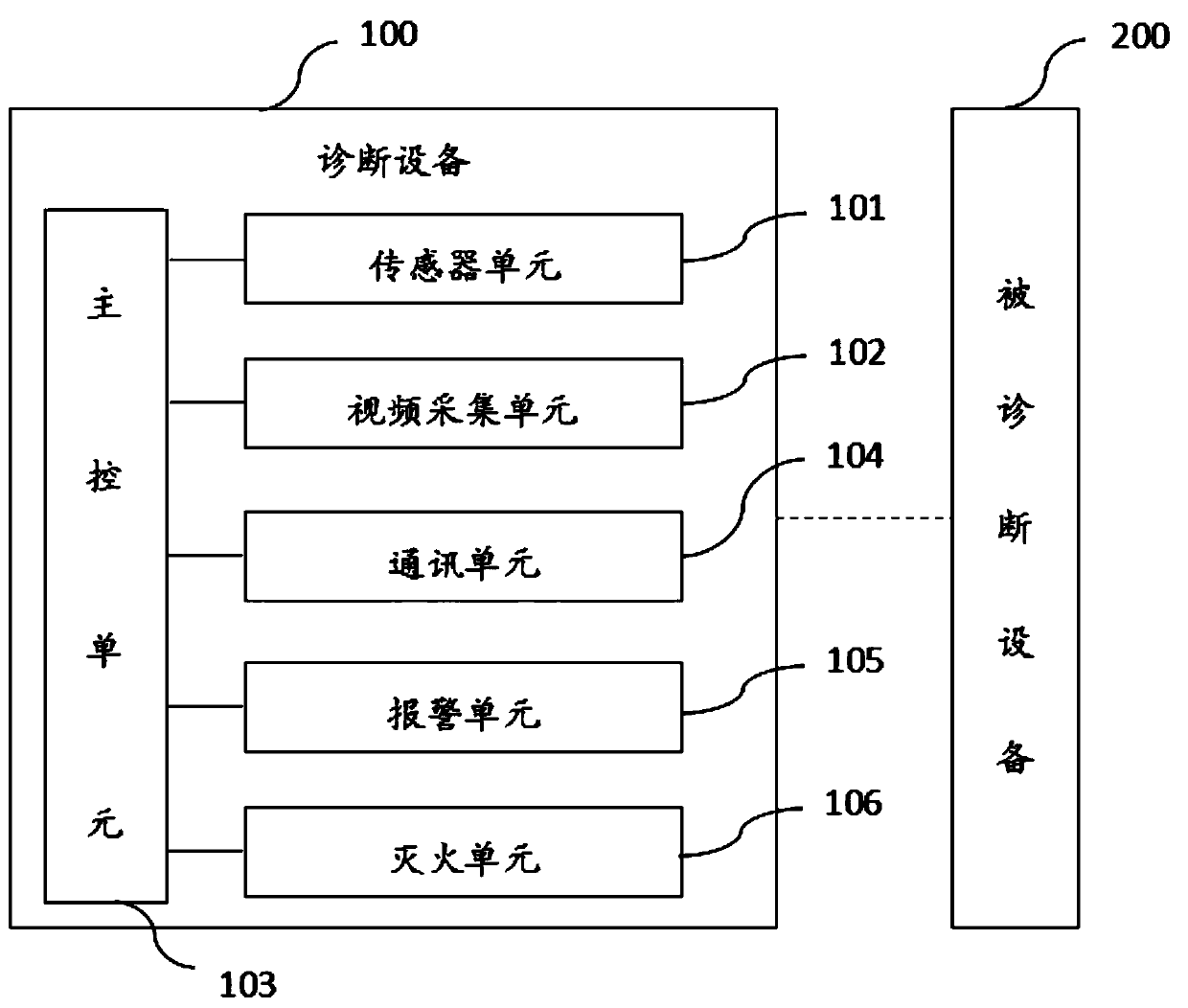
[0039] figure 1 The structure of the diagnostic system for industrial control equipment provided by Embodiment 1 of the present invention is shown. For the convenience of description, only the parts related to the embodiment of the present invention are shown, and the details are as follows:

[0040] Including diagnostic equipment 100 and diagnosed equipment 200; diagnostic equipment 100 includes:

[0041] The sensor unit 101 is used to detect the power voltage and current of the device under diagnosis 200, the temperature and humidity of the surrounding environment, and the temperature of the casing or the main board;

[0042]The video acquisition unit 102 is used to collect in real time the image of the status indicator light of the diagnosed device 200 or the image of the status display screen, or collect images of the appearance of the diagnosed device 200 and images of objects around the diagnosed device 200; Some old equipment without serial port communication, through ...

Embodiment 2

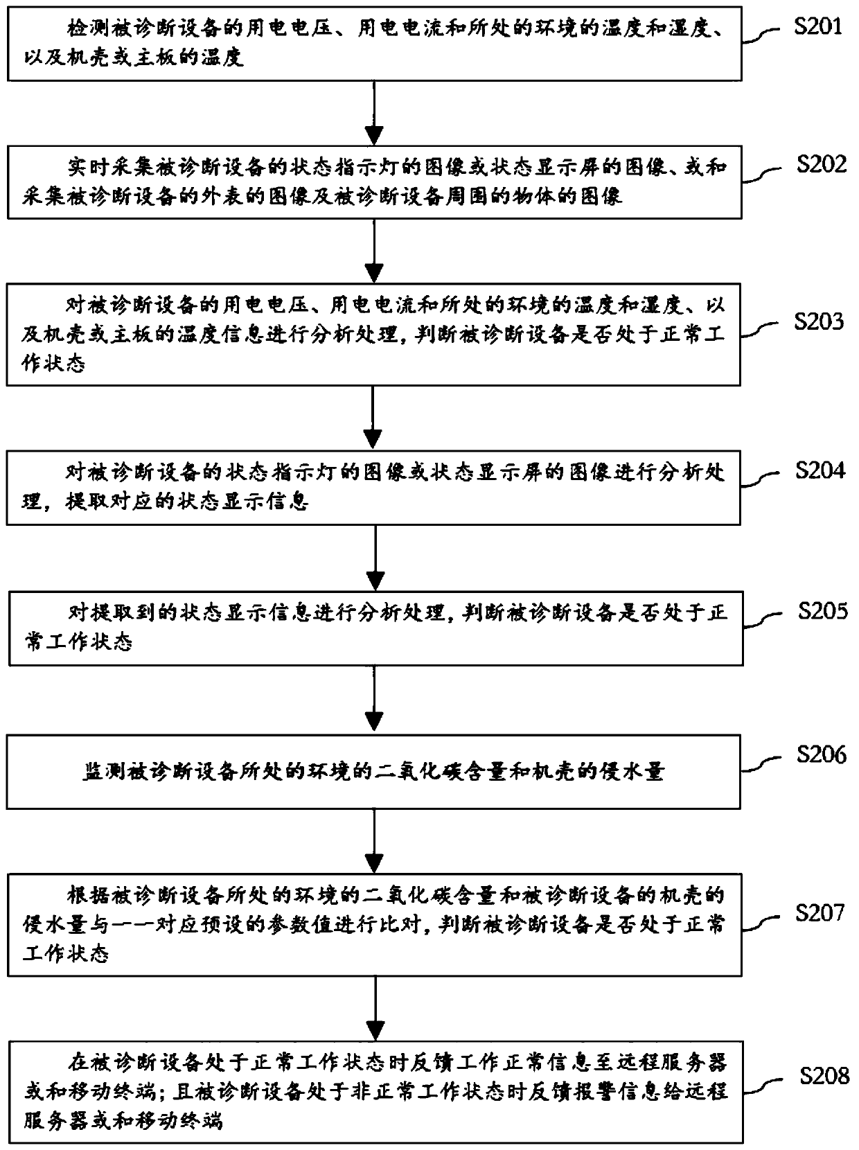
[0055] figure 2 The implementation process of the diagnostic method for industrial control equipment provided by the second embodiment of the present invention is shown. For the convenience of description, only the parts related to the embodiment of the present invention are shown, and the details are as follows:

[0056] In step S201, the power voltage and current of the device under diagnosis, the temperature and humidity of the surrounding environment, and the temperature of the casing or the main board are detected.

[0057] In step S202, the image of the status indicator light or the status display screen of the device under diagnosis is collected in real time, or the image of the appearance of the device under diagnosis and the images of objects around the device under diagnosis are collected.

[0058] In step S203, analyze and process the power voltage and current of the diagnosed device, the temperature and humidity of the environment, and the temperature information ...


PUM


Abstract

The invention is applicable to the technical field of diagnosis of industrial equipment, and provides a diagnosis method and a system for an industrial control device. The diagnosis method comprises steps of feeding normal working information back to a remote server or a mobile terminal when the diagnosed device is in a normal working state; feeding alarm information back to the remote server or the mobile terminal when the diagnosed device is in an abnormal working state and feeding voltage, current, ambient temperature and humidity of the currently diagnosed device, temperature information of a casing or a motherboard, an image of a status indicator and an image of a status display of the diagnosed device, an image of the appearance of the diagnosed device and images of objects around the diagnosed device back to the remote server or the mobile terminal, thereby realizing remote fault diagnosis. The diagnosis method greatly improves work efficiency and user experience and saves maintenance costs.

Description

technical field [0001] The invention belongs to the technical field of equipment diagnosis, and in particular relates to a diagnosis method and system for industrial control equipment. Background technique [0002] Industrial control equipment is used in more and more industries. When some old industrial control equipment without communication interface fails, there is no simple, intuitive, real-time search or display method in the prior art. [0003] Once the industrial control equipment fails, the maintenance personnel need to be notified to temporarily check the fault information at the fault point, which increases the difficulty of maintenance of the industrial control equipment and reduces the use efficiency of the industrial control equipment. Contents of the invention [0004] The purpose of the present invention is to provide a diagnostic method and system for industrial control equipment, aiming to solve the problem that users cannot remotely diagnose old equipmen...

Claims


Application Information

Patent Timeline
IPC IPC(8): G05B23/02
CPCG05B23/0262G05B2219/24065
Inventor 涂友冬
Owner 深圳市智微智能软件开发有限公司
Why Eureka
Try Eureka