Furnace lid of incinerator

A technology for incinerators and furnace covers, which is applied in the direction of incinerators, combustion methods, combustion types, etc., can solve the problems of temperature rise, deterioration of working environment, and affecting the working life of equipment, so as to achieve good cooling effect, improve working environment, Good sealing effect

Active Publication Date: 2015-07-08
宁波泰来环保设备有限公司
View PDF6 Cites 1 Cited by
  • Summary
  • Abstract
  • Description
  • Claims
  • Application Information

AI Technical Summary

Problems solved by technology

The existing vertical rotary pyrolysis gasification incinerator includes a furnace body, a furnace cover, a rotary platform and a support platform. The furnace body is located on the rotary platform and the furnace body rotates with the rotary platform. The support platform is fixed. The support platform is fixedly connected. The disadvantages of the existing technology are: because the furnace body rotates and the furnace cover does not rotate, it is difficult to achieve a good sealing effect at the joint surface between the furnace body and the furnace cover, and the internal temperature of the furnace body is very high, which can be as high as 1200 ℃ high temperature, the heat wave leaks from the joint surface between the furnace body and the furnace cover, which increases the temperature of the outer wall of the furnace, the outer wall of the furnace cover and the surrounding area, and affects the working life of the equipment; Only by standing on the furnace cover can we know the combustion status in the furnace body. After the temperature of the outer wall of the furnace cover rises, the working environment deteriorates. The working conditions in the incinerator cannot be adjusted in time to deal with it, which affects the combustion quality in the incinerator

Method used


Image

  • Furnace lid of incinerator
  • Furnace lid of incinerator
  • Furnace lid of incinerator

Examples


Embodiment Construction

[0020] The present invention will be further described below in conjunction with the accompanying drawings and specific embodiments.

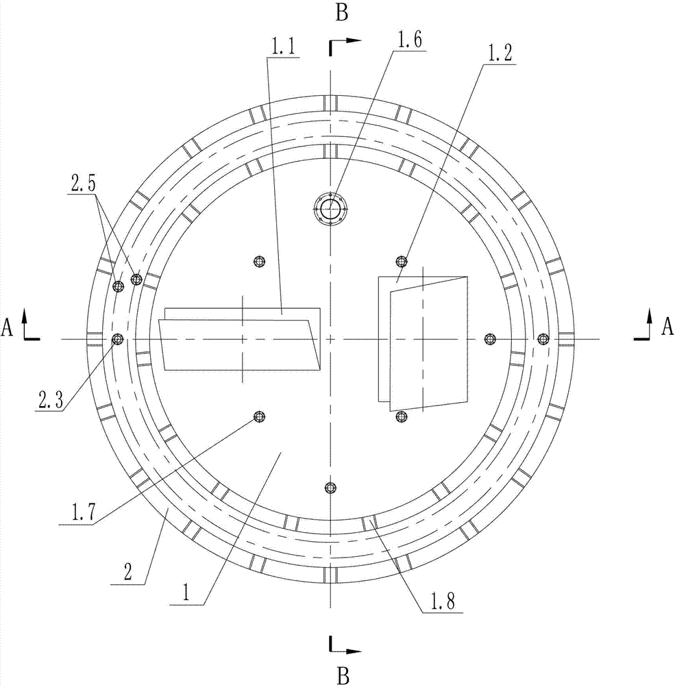
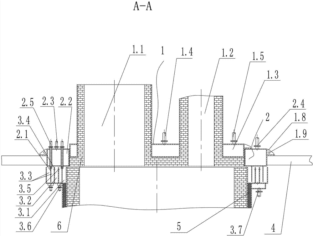
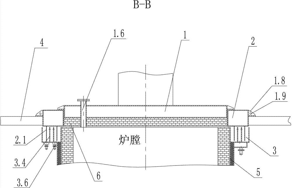
[0021] see Figure 1 ~ Figure 3 As shown, the incinerator cover of the present invention comprises a cover body 1 and an annular cover seat 2 connected with a support platform 4, the inner hole of the annular cover seat 2 is covered with a cover body 1, and the cover body 1 is provided with There is a feed port 1.1 and a flue port 1.2, and it also includes a sealed cooling seat 3 connected to the furnace body 5. At least one annular water tank is arranged inside the sealed cooling seat 3, and the opening of the annular water tank is upward; the cover seat 2 Located above the sealed cooling seat 3, the cover seat 2 is provided with a first cooling device, the bottom surface of the cover seat 2 is connected with at least one spacer ring 2.1, and the lower end of the spacer ring 2.1 is located in the annular water tank and together with the annula...


PUM


Abstract

The invention discloses a furnace lid of an incinerator. The furnace lid of the incinerator comprises a lid body (1) and an annular lid seat (2) which is connected with a support platform (4), wherein an inner hole of the annular lid seat (2) is provided with the lid body (1) in a sleeved mode, and a feeding port (1.1) and a flue port (1.2) are arranged on the lid body (1). The furnace lid of the incinerator further comprises an airtight cooling seat (3) connected with an incinerator body (5), wherein at least one annular water groove is formed in the airtight cooling seat (3), and an opening of the annular water groove faces upwards. The lid seat (2) is arranged above the airtight cooling seat (3), a first cooling device is arranged on the lid seat (2), at least one space ring (2.1) is connected with the bottom face of the lid seat (2), and the lower end of the space ring (2.1) is located inside the annular water groove and forms a labyrinth seal with the annular water groove. A second cooling device used for cooling is arranged on the lid body (1). The furnace lid of the incinerator is good in sealing effect, and can lower the temperature of the outer wall of the furnace lid and improve the working environment.

Description

technical field [0001] The invention belongs to the technical field of solid waste treatment engineering, and in particular relates to a furnace cover of a vertical rotary pyrolysis gasification incinerator. Background technique [0002] The vertical rotary pyrolysis gasification incinerator is a new type of waste treatment equipment. Although it appeared relatively late in the waste treatment industry, it has gained more and more attention due to its compact structure, low operating cost, and good exhaust emission effect. Many applications, and with the increasing improvement of technology, vertical pyrolysis gasification incinerator will become an important choice for small and medium domestic waste incineration power plants in the future. The existing vertical rotary pyrolysis gasification incinerator includes a furnace body, a furnace cover, a rotary platform and a support platform. The furnace body is located on the rotary platform and the furnace body rotates with the ...

Claims


Application Information

Patent Timeline
Patent Type & Authority Patents(China)
IPC IPC(8): F23G5/44
Inventor 刘玉山鲍海明
Owner 宁波泰来环保设备有限公司
Why Eureka
Try Eureka