
CPU heat dissipation installation structure for reinforced server

A technology for installation structure and server, which is applied in the direction of instruments, electrical digital data processing, digital data processing components, etc., can solve the problems of poor CPU cooling effect and poor cooling effect, etc., and achieves reliable installation structure, simple and compact structure, The effect of improving heat dissipation efficiency

Pending Publication Date: 2019-11-15
合肥恒研智能科技有限公司
View PDF0 Cites 0 Cited by
  • Summary
  • Abstract
  • Description
  • Claims
  • Application Information

AI Technical Summary

Problems solved by technology

At present, the existing reinforced server body is usually a square box structure, and the fan on one side is usually used to dissipate heat from the internal components. Because there are partitions for various installation components in the chassis, the heat dissipation effect is not good.
Among them, especially for the core components of the hardened server, that is, the cooling effect of the CPU on the motherboard is not good, and needs to be improved urgently.

Method used


Image

  • CPU heat dissipation installation structure for reinforced server
  • CPU heat dissipation installation structure for reinforced server
  • CPU heat dissipation installation structure for reinforced server

Examples


Embodiment Construction

[0029] In order to make the purpose, technical solutions and advantages of the embodiments of the present invention clearer, the technical solutions in the embodiments of the present invention will be clearly and completely described below in conjunction with the embodiments of the present invention. Obviously, the described embodiments are part of the present invention Examples, not all examples. Based on the embodiments of the present invention, all other embodiments obtained by persons of ordinary skill in the art without creative efforts fall within the protection scope of the present invention.

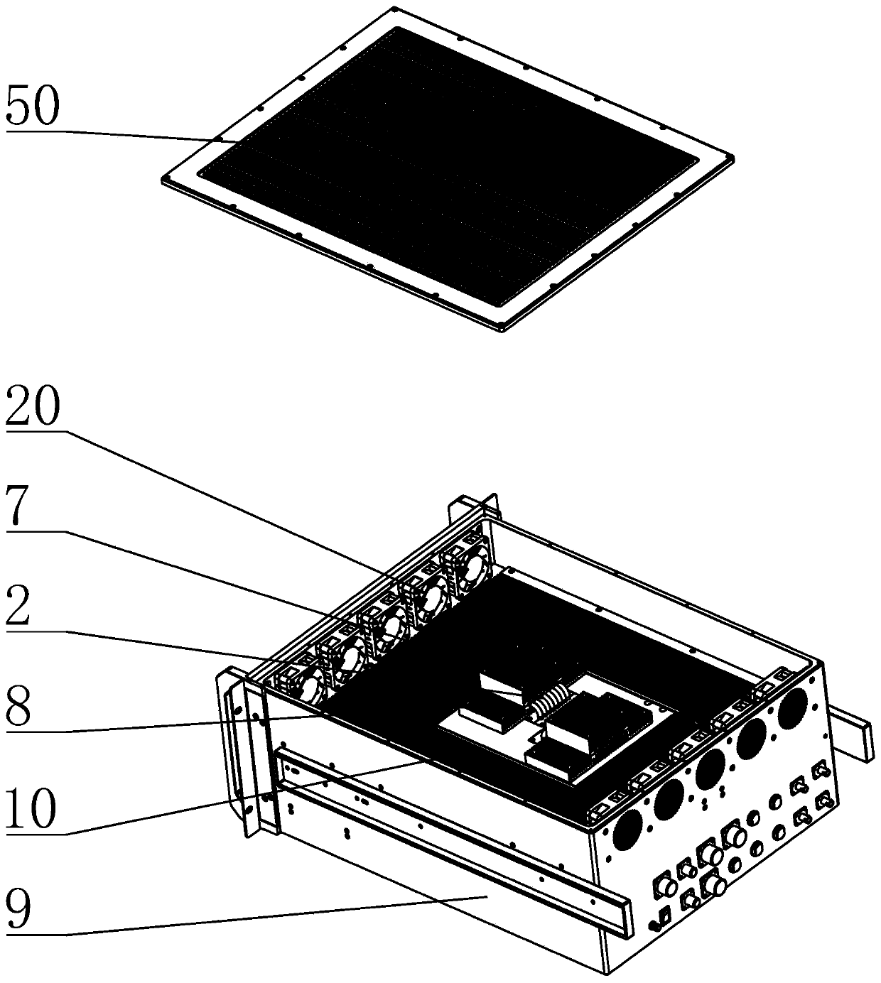
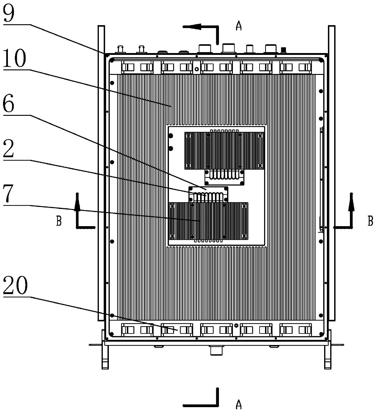
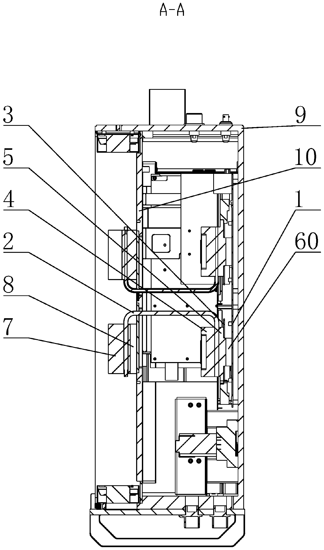
[0030] combined with Figure 1 to Figure 7 , the present invention is further described:

[0031] A CPU heat dissipation installation structure for reinforcing a server, including a main board 1, a heat dissipation copper pipe 2, a buckle 3, a heat conduction upper pressure block 4, a heat conduction lower pressure block 5, a transition block 6, a heat dissipation upper pressure...


PUM


Abstract

The invention provides a CPU heat dissipation mounting structure for a reinforced server. A mainboard is positioned at the bottom of a case of the reinforced server; a buckle is positioned at the periphery of the CPU on the mainboard; the heat conduction lower pressing block is positioned on the buckle and is in contact with the CPU to realize heat conduction; the heat conduction upper pressing block is positioned on the heat conduction lower pressing block, and the lower end connecting part of the heat dissipation copper pipe is clamped and positioned; the upper end connecting part of the heat dissipation copper pipe is positioned on the partition plate through a transition block; the heat dissipation lower pressing block is positioned on the partition plate; the heat dissipation upper pressing block is positioned on the heat dissipation lower pressing block, so that the upper end connecting part of the heat dissipation copper pipe is clamped and positioned; the partition plate divides a case of the reinforced server into an upper cavity structure and a lower cavity structure, and fan assemblies are further arranged in the upper cavity structure; and the fan assemblies are oppositely arranged on the two sides of the case correspondingly, so that heat dissipation of the heat dissipation upper pressing block and the heat dissipation lower pressing block is achieved through air channels formed by the fan assemblies, and the heat dissipation efficiency of the CPU is greatly improved.

Description

technical field [0001] The invention relates to the technical field of hardened servers, in particular to a CPU cooling installation structure for hardened servers. Background technique [0002] At present, in fields such as national defense, transportation, news, geology, medical treatment, mining, firefighting, and rescue, there is a great demand for vehicle-mounted hardened servers. Due to the particularity of the working environment, the vehicle-mounted server requires not only powerful processing capabilities, but also good EMC performance, anti-vibration, shock resistance, etc. Commercial computers that are generally popular in the market do not have this kind of performance. At present, the existing reinforced server body is usually a square box structure, and a fan on one side is usually used to dissipate heat from internal components. Since there are partitions for various installation components in the chassis, the heat dissipation effect is not good. Among them,...

Claims


Application Information

Patent Timeline
Patent Type & Authority Applications(China)
IPC IPC(8): G06F1/20G06F1/18
CPCG06F1/206G06F1/184G06F1/185Y02D10/00
Inventor 王永战
Owner 合肥恒研智能科技有限公司
Learn More