Conveyor belt

A technology for conveyor belts and belt bundles, applied in the field of conveyor belts, can solve the problems of low wear resistance, unfavorable durability, and increased material costs, and achieve the effects of not easy peeling, seeking durability, and inhibiting interface peeling.

Active Publication Date: 2019-11-15
THE YOKOHAMA RUBBER CO LTD
View PDF11 Cites 1 Cited by
  • Summary
  • Abstract
  • Description
  • Claims
  • Application Information

AI Technical Summary

Problems solved by technology

[0010] However, although the conveyor belt using a flame-retardant rubber material has the effect of suppressing damage caused by heat, the material cost tends to increase, and in addition, the wear resistance is not high, so there is a disadvantage in ensuring durability.

Method used


Image

  • Conveyor belt
  • Conveyor belt
  • Conveyor belt

Examples


no. 1 approach

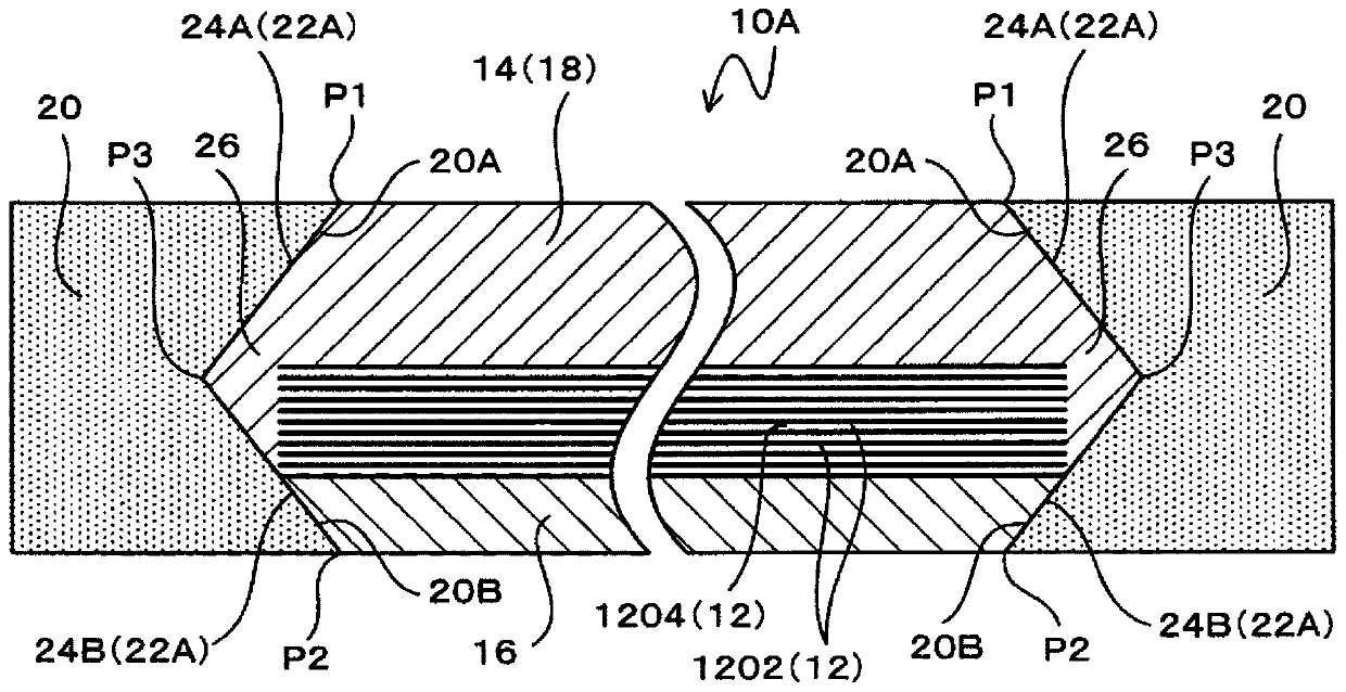
[0035] First, refer to figure 1 The description will start with the first embodiment.

[0036] The conveyor belt 10A includes a belt main body 18, a flame-retardant rubber portion 20, and a joint area increasing portion 22A.

[0037] The belt main body 18 is configured to include a core reinforcing layer 12 , an upper surface protective rubber layer 14 , and a lower surface protective rubber layer 16 .

[0038] The core reinforcement layer 12 is configured to include a plurality of core materials 1202 and a coating rubber 1204 covering the core materials 1202 .

[0039] Conventionally known various materials such as steel cords, canvas, and organic fibers can be used as the core material 1202 , but steel cords are used as the core material 1202 in the present embodiment.

[0040] The core reinforcement layer 12 is a portion that supports the tensile load applied to the conveyor belt 10A and maintains the tension of the conveyor belt 10A.

[0041] The upper surface protectiv...

no. 2 approach

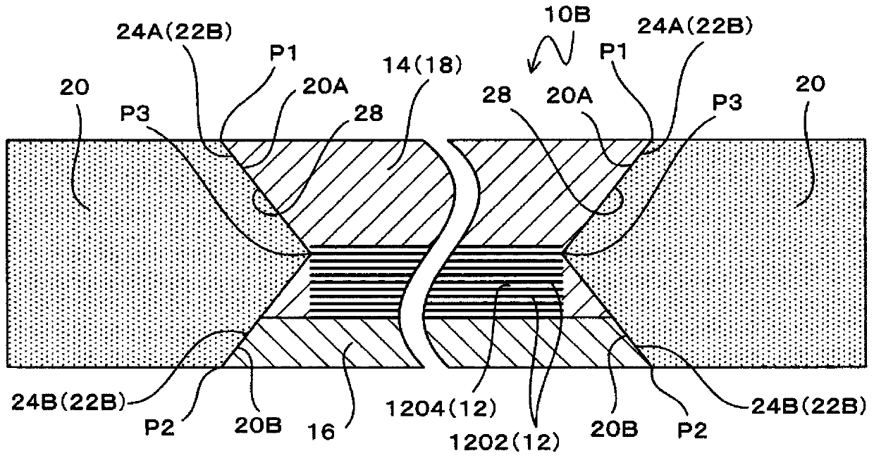
[0063] Next, refer to figure 2 A second embodiment will be described.

[0064] It should be noted that, in the description of the following embodiment, the same parts as those of the first embodiment are given the same reference numerals and their descriptions are omitted, and the different points will be described emphatically.

[0065] In the conveyor belt 10B of the second embodiment, recessed portions 28 are formed on both side portions of the belt main body 18 to protect the lower surface of the rubber layer 16 from the upper surface of the upper surface protective rubber layer 14 and the lower surface of the lower surface of the rubber layer 16 . The thickness of the belt main body 18 is gradually reduced to the center of the width direction of the belt main body 18 , and the flame-retardant rubber part 20 is embedded.

[0066] More specifically, the upper inclined surface 24A is formed on the upper surface protective rubber layer 14 so that both ends in the width dire...

no. 3 approach

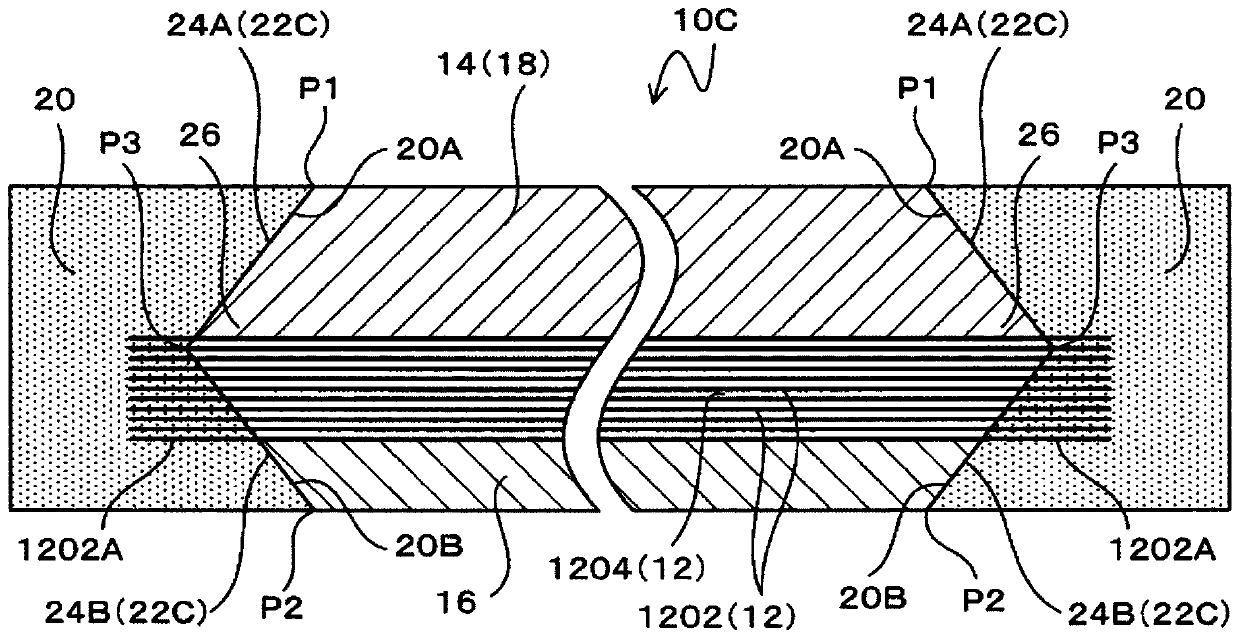
[0073] Next, refer to image 3 A third embodiment will be described.

[0074] The conveyor belt 10C of the third embodiment is a modified example of the first embodiment, and the configuration of the joint area increasing portion 22C is different from that of the first embodiment.

[0075] That is, on both sides in the width direction of the core reinforcement layer 12, a plurality of core material protrusions 1202A in which the core material 1202 protrudes from the coating rubber 1204 and is embedded in the flame-retardant rubber part 20 is provided, and the joint area increasing part 22C is configured to include Core protrusion 1202A.

[0076] That is, the joint area increasing portion 22C is composed of the upper and lower inclined surfaces 24A, 24B constituting the surface of the convex portion 26 and the plurality of core materials 1202 constituting the core material protruding portion 1202A.

[0077] In the third embodiment, the upper inclined surface 24A is formed on ...


PUM


Abstract

The present invention maintains the bonding strength of a flame-retardant rubber, minimizes damage caused by heat, and improves durability. In this conveyor belt, a bonding surface area-increasing section 22A is provided to a belt body 18 and is configured to include a total of two upper and lower inclined surfaces 24A, 24B that are inclined with respect to both the thickness direction and the width direction of the belt body 18 and that are oriented in opposite directions from each other. The upper inclined surface 24A is formed so that when both ends of the upper surface of an upper surfacecover rubber layer 14 in the width direction are designated as start points P1, said upper inclined surface 24A is increasingly displaced in a direction approaching the lower surface of a lower surface cover rubber layer 14 from the starting points P1 to both ends of the conveyor belt 10A in the width direction. The lower inclined surface 24B is formed so that when both ends of the lower surface of the lower surface cover rubber layer 16 in the width direction are designated as start points P2, said lower inclined surface 24B is increasingly displaced in a direction approaching the upper surface of the upper surface cover rubber layer 14 from the starting points P2 to both ends of the conveyor belt 10A in the width direction.

Description

technical field [0001] The present invention relates to a conveyor belt. Background technique [0002] In mines, quarries, civil engineering construction sites, etc., belt conveyors are widely used to transport coal, ore, earth and sand, etc. to be conveyed. [0003] The belt conveyor device includes an elongated frame, a conveyor belt stretched over both ends in the longitudinal direction of the frame, a plurality of guide rollers supporting the conveyor belt, and a drive unit for running the conveyor belt. [0004] Furthermore, guides provided on the frame extend along the extending direction of the conveyor belt on both sides of the conveyance surface of the conveyor belt. [0005] In such a belt conveyor device, objects to be conveyed are loaded at a position deviated from the center in the width direction of the conveyor belt, whereby the conveyor belt in operation is zigzag. [0006] When the conveyor belt bends, the edge of the conveyor belt continues to be in conta...

Claims


Application Information

Patent Timeline
Patent Type & Authority Applications(China)
IPC IPC(8): B65G15/34
CPCB65G15/34
Inventor 宫岛纯
Owner THE YOKOHAMA RUBBER CO LTD
Why Eureka
Try Eureka