Air conditioner
A technology for air-conditioning devices and air-conditioning housings, applied in air-conditioning systems, transportation and packaging, components of pumping devices for elastic fluids, etc., capable of solving problems such as low noise reduction effect and turbulent air flow
- Summary
- Abstract
- Description
- Claims
- Application Information
AI Technical Summary
Problems solved by technology
Method used
Image
Examples
no. 1 approach
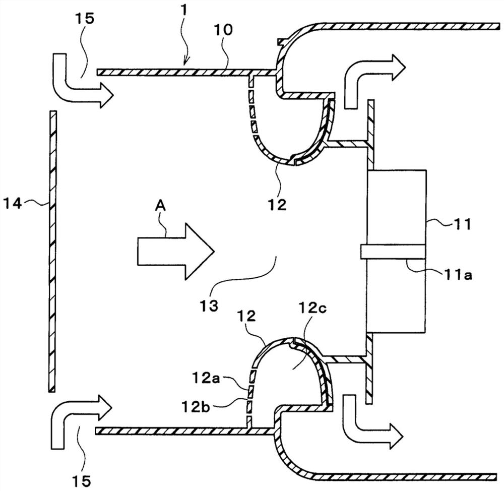
[0018] Hereinafter, the first embodiment will be described using the drawings. Such as figure 1 As shown, the vehicle air conditioner 1 according to the present embodiment includes an air conditioner case 10 . The air conditioner case 10 constitutes an air passage for air blown into the vehicle interior. exist figure 1 In , the direction from left to right is the air flow direction A. Although in figure 1 Although the illustration is omitted, a heat exchanger and the like for adjusting the temperature of the air are provided inside the air conditioner case 10 .
[0019] A blower fan 11 is provided at a central portion inside the air conditioner case 10 . The blower fan 11 blows air toward the vehicle interior. The blower fan 11 of this embodiment is a centrifugal fan, and is comprised as the electric blower driven by a motor. The blower fan 11 is arranged such that the rotation axis 11a is parallel to the air flow direction A. As shown in FIG.
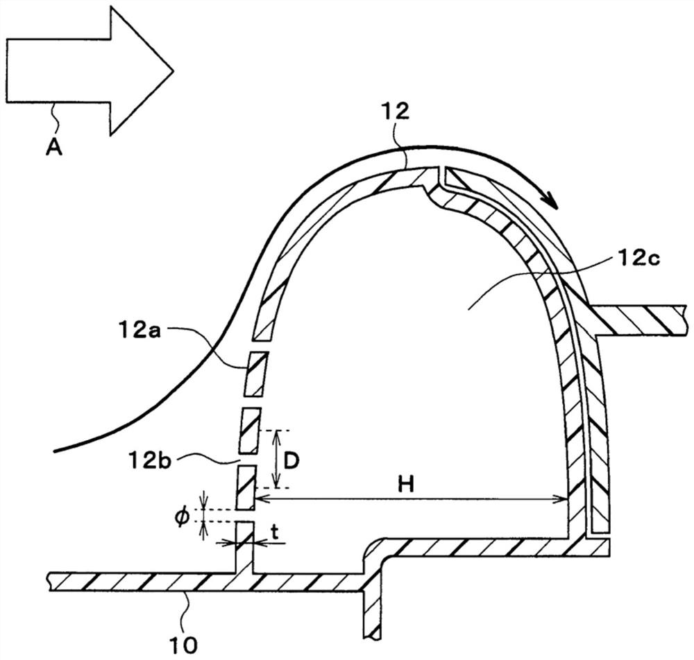
[0020] A bellmouth 12 i...
no. 2 approach
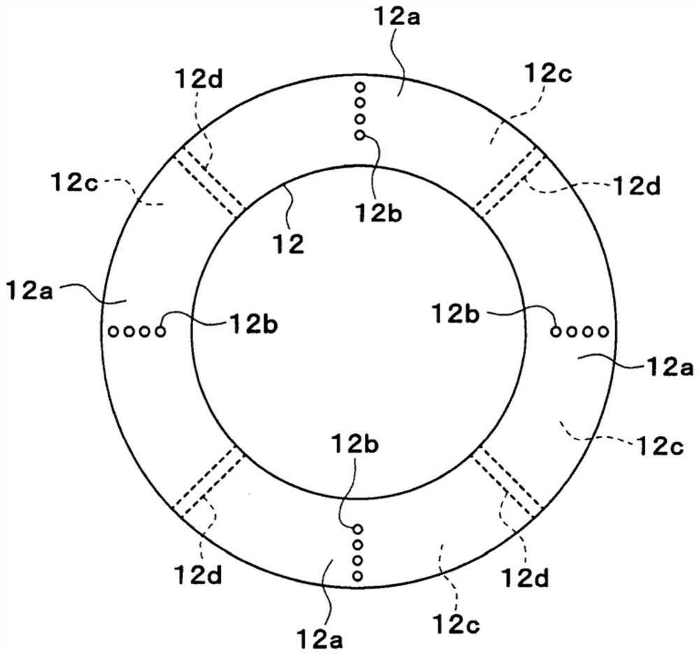
[0044] Next, use image 3 A second embodiment will be described.
[0045] Such as image 3 As shown, in the second embodiment, a plurality of closed spaces 12c of bellmouths 12 are provided. Specifically, the partition part 12d is provided in the inside of the bellmouth 12, and the closed space 12c is divided into several. Through-holes 12b are formed in each of the divided closed spaces 12c. A plurality of resonators can be constituted by each divided closed space 12c and the corresponding through-holes 12b.
[0046] In each of the plurality of closed spaces 12c, the resonance frequencies of the plurality of resonators can be made different by varying the size of the through-holes 12b, the interval between adjacent through-holes 12b, the aperture ratio of the through-holes 12b, and the like. As a result, noise of a plurality of frequencies generated with the rotation of the blower fan 11 can be resonated and absorbed by a plurality of resonators. Accordingly, even in the...
no. 3 approach
[0048] Next, use Figure 4 A third embodiment will be described.
[0049] Such as Figure 4 As shown, in the third embodiment, the through hole 12 b formed in the bell mouth 12 is inclined with respect to the air flow direction A and the rotation axis 11 a of the blower fan 11 . exist Figure 4 In the example shown, the air flow direction A is the horizontal direction, and the axial center of the through-hole 12b is inclined with respect to the horizontal direction. Specifically, the through-hole 12b is inclined from the bottom to the top as it goes from the upstream side to the downstream side in the air flow direction A, and is in a state of being low in front and high in back.
[0050] Thus, forming the through-hole 12b so that the front is low and the rear is high makes it difficult for water to enter the closed space 12c through the through-hole 12b when moisture exists inside the air-conditioning case 10 . Since the closed space 12c does not communicate with the outs...
PUM
 Abstract
Description
Claims
Application Information
 - R&D
- Intellectual Property
- Life Sciences
- Materials
- Tech Scout
- Unparalleled Data Quality
- Higher Quality Content
- 60% Fewer Hallucinations
Browse by: Latest US Patents, China's latest patents, Technical Efficacy Thesaurus, Application Domain, Technology Topic, Popular Technical Reports.
© 2025 PatSnap. All rights reserved.Legal|Privacy policy|Modern Slavery Act Transparency Statement|Sitemap|About US| Contact US: help@patsnap.com


