Static mixer for an exhaust gas system of an internal combustion engine

a technology of internal combustion engine and exhaust gas system, which is applied in the direction of flow mixer, exhaust treatment, mixer, etc., can solve the problems of undesirable backflow effects, inability to achieve sufficient mixing of gaseous reduction agents with the exhaust gas stream, and inability to achieve the described mixers, etc., to avoid turbulent flows and pressure losses. , the effect of simple structur

Inactive Publication Date: 2011-08-25
IAV INGGES AUTO & VERKEHR
View PDF12 Cites 78 Cited by
  • Summary
  • Abstract
  • Description
  • Claims
  • Application Information

AI Technical Summary

Benefits of technology

[0014]Due to the placement of flow guide devices, the inclined front sections of which are disposed alternately facing in different directions, and by means of the configuration and placement of the fluid passage spaces, which are delimited by guide elements, intensive and homogeneous mixing of two different fluid streams is achieved, while avoiding turbulent flows and pressure losses. Mixing of the fluid streams is supported by guide vanes that are disposed on the flow guide elements in the front region of the central center element, and on a frame that delimits the inclined sections of the flow guide elements.
[0015]Another advantage of the mixer according to the invention consists in its relatively simple structure, because the main components are formed by correspondingly bent metal sheets and are connected with one another in terms of material.

Problems solved by technology

When gaseous reduction agents are used, sufficient mixing of the gaseous reduction agent with the exhaust gas stream is not possible with the mixers described.
Another disadvantage of the mixers is that turbulent flows occur as the result of the flow guide elements or the blades, and these can lead to undesirable back-flow effects.
Furthermore, the back-flow effects have a negative impact on the pressure loss above the mixer.

Method used


Image

  • Static mixer for an exhaust gas system of an internal combustion engine
  • Static mixer for an exhaust gas system of an internal combustion engine
  • Static mixer for an exhaust gas system of an internal combustion engine

Examples


Embodiment Construction

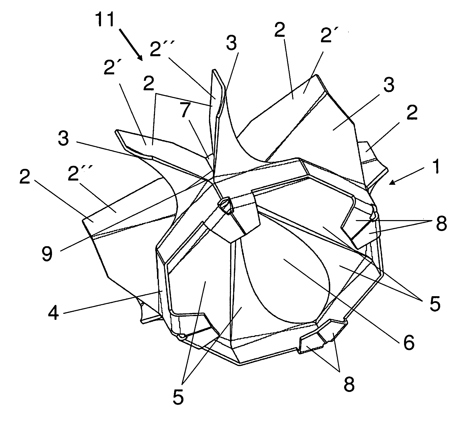
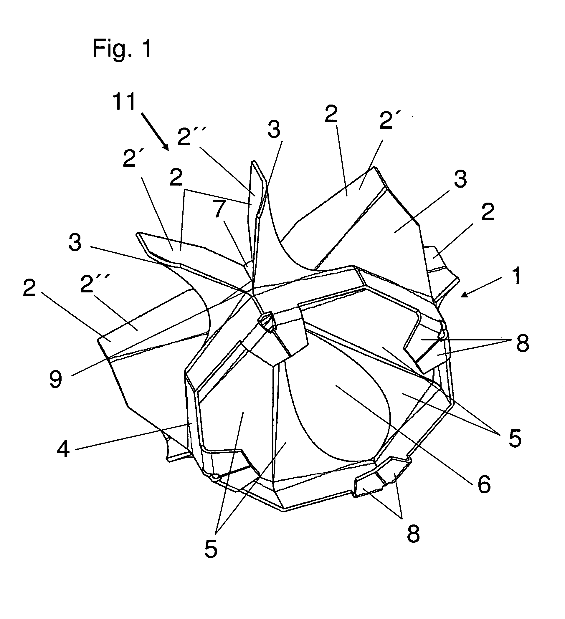
[0023]Referring now in detail to the drawings, a mixer 1 according to the invention, for mixing the exhaust gases of an internal combustion engine with a reduction agent that is supplied to the exhaust gas stream, is shown in FIG. 1, in perspective. In this connection, the reduction agent is preferably a gaseous substance, such as gaseous ammonia, for example. It is also possible to mix a liquid reduction agent with the exhaust gas stream using mixer 1 according to the invention. In the following, the exhaust gas stream and the supplied reduction agent are referred to as a fluid stream. The flow direction 11 of the fluid flow is indicated with a corresponding arrow in the drawings. Mixer 1 is disposed in an exhaust gas pipe, not shown, of an internal combustion engine, in known manner.

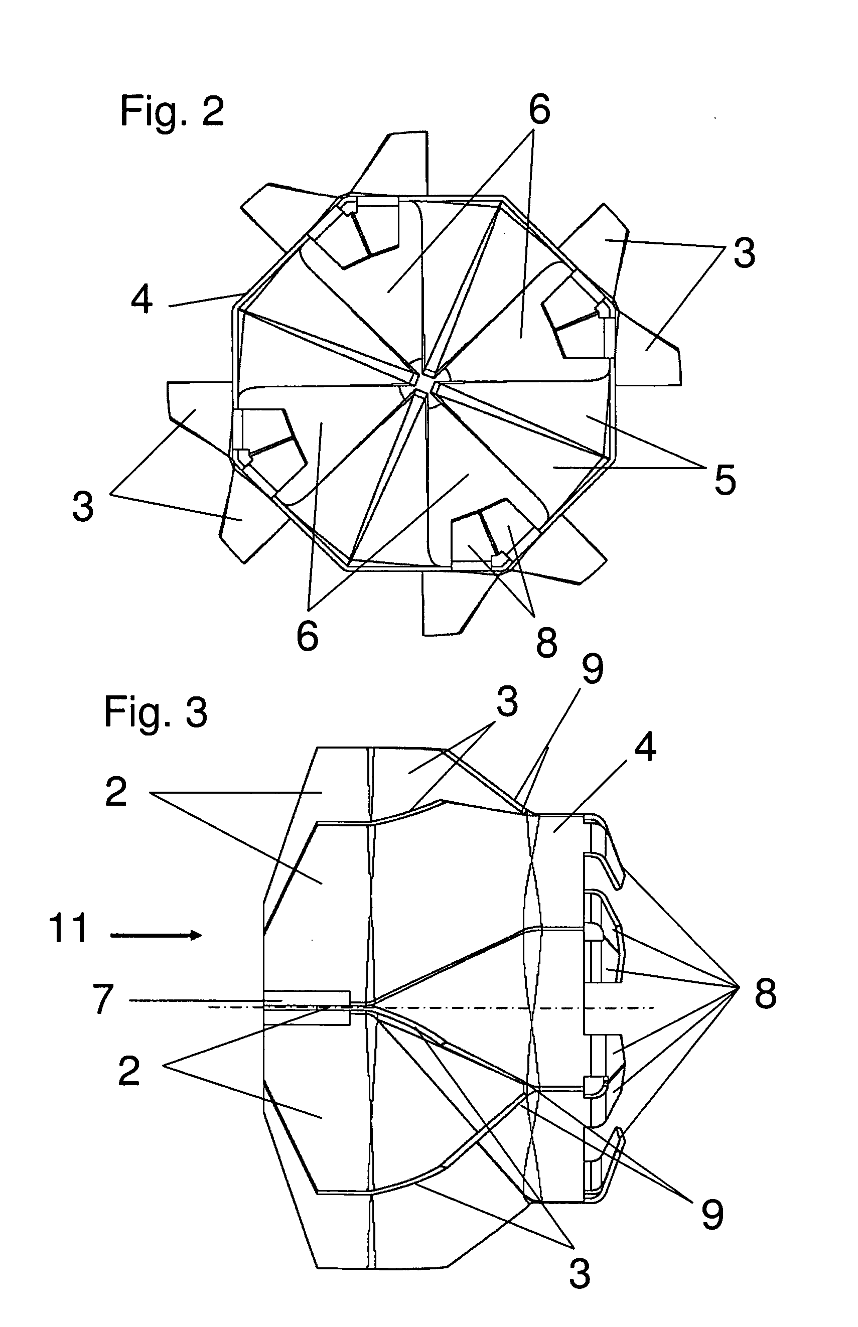
[0024]Mixer 1 consists of a plurality of flow guide elements 2 that influence the fluid stream, which elements are axially disposed around a central center element 7 and extend in the direction of the ...


PUM


Abstract

A static mixer for an exhaust gas system of an internal combustion engine with which at least two different fluid streams are mixed almost homogeneously after a short mixing distance, and with which back-flow effects and pressure losses are avoided, to the greatest possible extent. Due to the placement of flow guide devices, the inclined front sections of which are disposed alternately facing in different directions, and by the configuration and placement of the fluid passage spaces, which are delimited by guide elements, intensive and homogeneous mixing of two different fluid streams is achieved, while avoiding turbulent flows and pressure losses. Mixing of the fluid streams is supported by guide vanes that are disposed on the flow guide elements in the front region of the central center element, and on a frame that delimits the inclined sections of the flow guide elements.

Description

CROSS REFERENCE TO RELATED APPLICATIONS[0001]Applicant claims priority under 35 U.S.C. 119 of German Application No. 10 2010 009 043.3 filed on Feb. 23, 2010.BACKGROUND OF THE INVENTION[0002]1. Field of the Invention[0003]The invention relates to a static mixer for an exhaust gas system of an internal combustion engine which is disposed in an exhaust gas pipe of the internal combustion engine and which consists of a plurality of flow guide elements that influence the flow of a fluid stream. The flow guide elements are disposed on a central center element and extend outwardly in the direction of the inner wall of the exhaust gas pipe. The flow guide elements have a section in the flow direction of the fluid stream that is inclined at a predetermined angle relative to the flow guide elements.[0004]2. The Prior Art[0005]It is known that the reduction of nitrogen oxide emissions of the exhaust gases of an internal combustion engine takes place by means of selective catalytic reduction (...

Claims


Application Information

Patent Timeline
Patent Type & Authority Applications(United States)
IPC IPC(8): B01F5/06
CPCB01F5/0616F01N2240/20F01N3/2892B01F25/4315
Inventor GENTGEN, HOLGER
Owner IAV INGGES AUTO & VERKEHR
Why Eureka
Try Eureka