Air conditioning device

A technology for air-conditioning devices and air-conditioning shells, which is applied to air-conditioning systems, transportation and packaging, and parts of pumping devices for elastic fluids. Effect

Active Publication Date: 2019-11-15
DENSO CORP
View PDF10 Cites 0 Cited by
  • Summary
  • Abstract
  • Description
  • Claims
  • Application Information

AI Technical Summary

Problems solved by technology

[0008] However, in the blower described in Patent Document 1, although the noise reduction effect on the noise generated by the blower fan itself is obtained, the noise reduction effect on the noise generated upstream of

Method used


Image

  • Air conditioning device
  • Air conditioning device
  • Air conditioning device

Examples


no. 1 approach

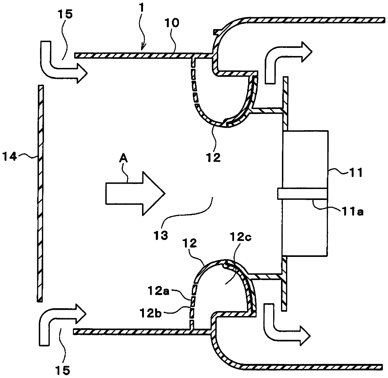
[0018] Hereinafter, the first embodiment will be described using the drawings. like figure 1 As shown, the vehicle air conditioner 1 according to the present embodiment includes an air conditioner case 10 . The air conditioner case 10 constitutes an air passage for air blown into the vehicle interior. exist figure 1 In , the direction from left to right is the air flow direction A. Although in figure 1 Although the illustration is omitted, a heat exchanger and the like for adjusting the temperature of the air are provided inside the air conditioner case 10 .

[0019] A blower fan 11 is provided at a central portion inside the air conditioner case 10 . The blower fan 11 blows air toward the vehicle interior. The blower fan 11 of this embodiment is a centrifugal fan, and is comprised as the electric blower driven by a motor. The blower fan 11 is arranged such that the rotation axis 11a is parallel to the air flow direction A. As shown in FIG.

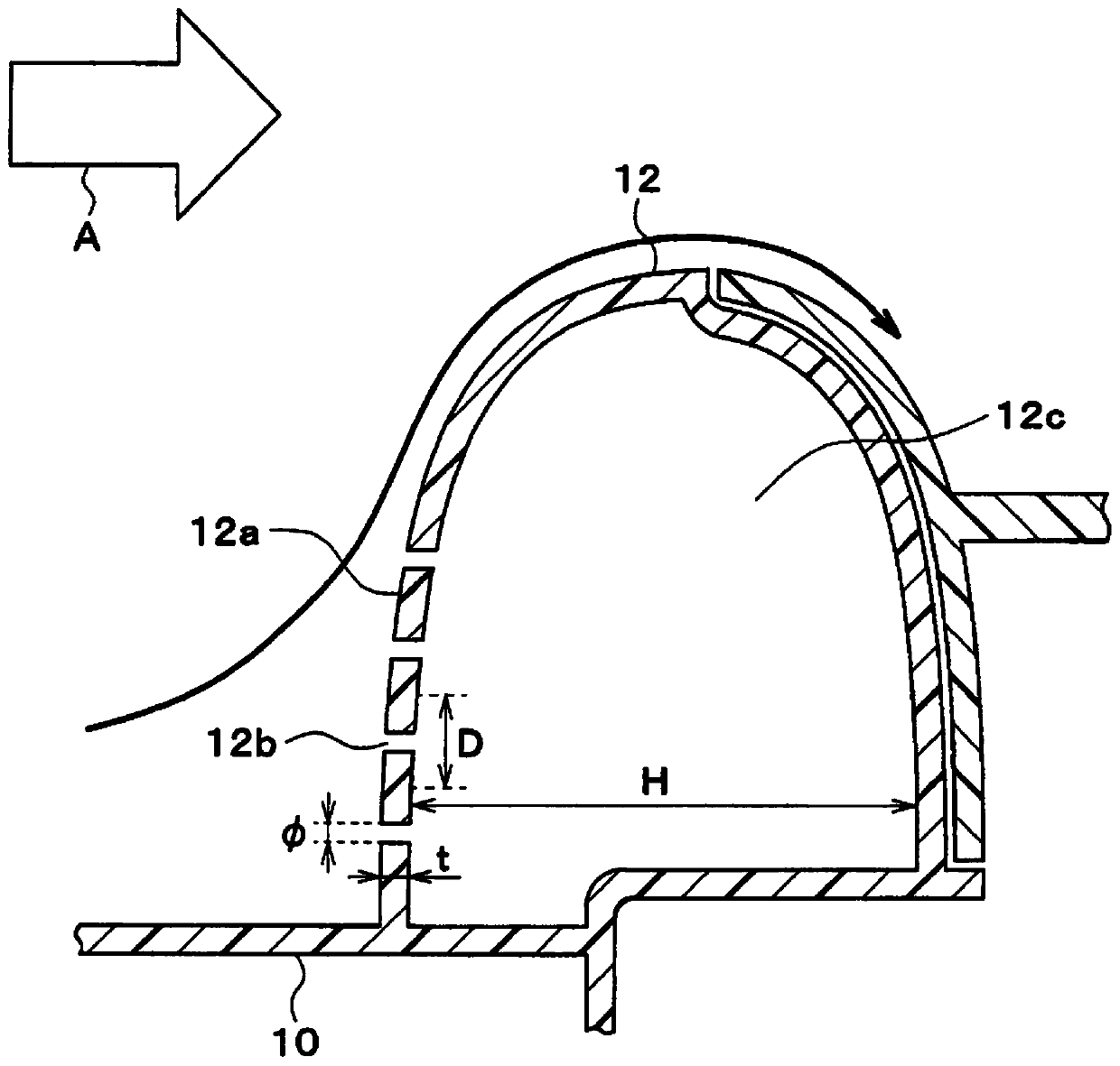
[0020] A bellmouth 12 is p...

no. 2 approach

[0044] Next, use image 3 A second embodiment will be described.

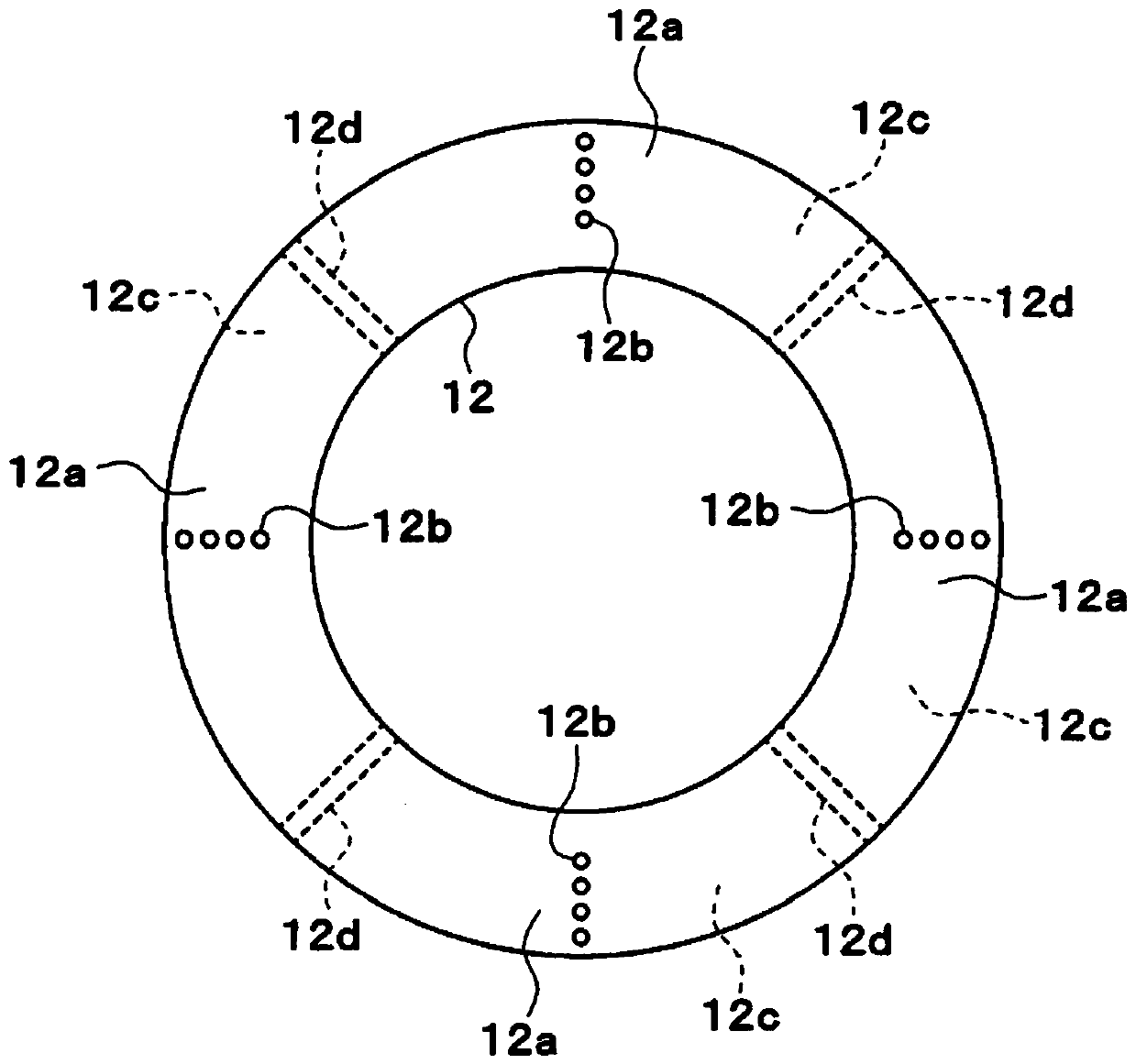
[0045] Such as image 3 As shown, in the second embodiment, a plurality of closed spaces 12c of bellmouths 12 are provided. Specifically, the partition part 12d is provided in the inside of the bellmouth 12, and the closed space 12c is divided into several. Through-holes 12b are formed in each of the divided closed spaces 12c. A plurality of resonators can be constituted by each divided closed space 12c and the corresponding through-holes 12b.

[0046] In each of the plurality of closed spaces 12c, the resonance frequencies of the plurality of resonators can be made different by varying the size of the through-holes 12b, the interval between adjacent through-holes 12b, the aperture ratio of the through-holes 12b, and the like. As a result, noise of a plurality of frequencies generated with the rotation of the blower fan 11 can be resonated and absorbed by a plurality of resonators. Accordingly, even in the...

no. 3 approach

[0048] Next, use Figure 4 A third embodiment will be described.

[0049] Such as Figure 4 As shown, in the third embodiment, the through hole 12 b formed in the bell mouth 12 is inclined with respect to the air flow direction A and the rotation axis 11 a of the blower fan 11 . exist Figure 4 In the example shown, the air flow direction A is the horizontal direction, and the axial center of the through-hole 12b is inclined with respect to the horizontal direction. Specifically, the through-hole 12b is inclined from the bottom to the top as it goes from the upstream side to the downstream side in the air flow direction A, and is in a state of being low in front and high in back.

[0050] Thus, forming the through-hole 12b so that the front is low and the rear is high makes it difficult for water to enter the closed space 12c through the through-hole 12b when moisture exists inside the air-conditioning case 10 . Since the closed space 12c does not communicate with the outs...


PUM


Abstract

An air conditioning device has an air conditioning case (10), a blower fan (11), and a facing wall (14). The air conditioning case constitutes an air passage through which air to be delivered to a room interior flows. The blower fan is disposed within the air conditioning case. The facing wall is provided upstream of the blower fan in the direction of air flow and is disposed facing the intake opening of the blower fan. The air conditioning case has a facing surface (12a) facing the facing wall and having a through-hole (12b) formed therein. The air conditioning case has formed therein a closed space (12c) formed on the opposite side of the facing surface from the air passage and in communication with the air passage through the through-hole. The through-hole and the closed surface form aresonator having a predetermined resonance frequency.

Description

[0001] Cross-references to related applications [0002] This application is based on JP Patent application No. 2017-54344 for which it applied on March 21, 2017, The disclosure content is incorporated in this application by reference. technical field [0003] The present invention relates to an air conditioner equipped with a blower fan. Background technique [0004] In an air conditioner equipped with a blower fan, noise is generated as the blower fan rotates. Therefore, in Patent Document 1, it is proposed to reduce noise by using a bellmouth resonator. In this blower, a resonator composed of an opening and a cavity communicating with the opening is provided in the bellmouth, and the resonant frequency of the resonator is made to match the frequency of noise accompanying the rotation of the blower fan, thereby reducing noise. [0005] prior art literature [0006] patent documents [0007] Patent Document 1: Japanese Patent Application Laid-Open No. 10-227299 [0008...

Claims


Application Information

Patent Timeline
IPC IPC(8): F04D29/44B60H1/00F04D29/66F24F1/0022
CPCB60H2001/006B60H2001/00085B60H1/00514B60H1/00021
Inventor 小坂翔加藤慎也
Owner DENSO CORP
Why Eureka
Try Eureka