Projection optical system, image projection device and image projection system

A technology of projection optical system and optical system, which is applied to optics, projection devices, optical components, etc., can solve the problem of large distance from the first reflection surface to the second reflection surface, and achieve the effect of reducing image distortion

Inactive Publication Date: 2019-11-15
PANASONIC INTELLECTUAL PROPERTY MANAGEMENT CO LTD
View PDF3 Cites 4 Cited by
  • Summary
  • Abstract
  • Description
  • Claims
  • Application Information

AI Technical Summary

Problems solved by technology

[0003] However, in the projection device described in Patent Document 1, the distance from the first reflection surface to the second reflection surface is relatively large.
Therefore, it leads to an increase in the size of the projection device (higher profile)

Method used


Image

  • Projection optical system, image projection device and image projection system
  • Projection optical system, image projection device and image projection system
  • Projection optical system, image projection device and image projection system

Examples


Embodiment approach

[0026] Below, use Figure 1 to Figure 10 The image projection system 1 and the image projection device 10 of the present disclosure will be described.

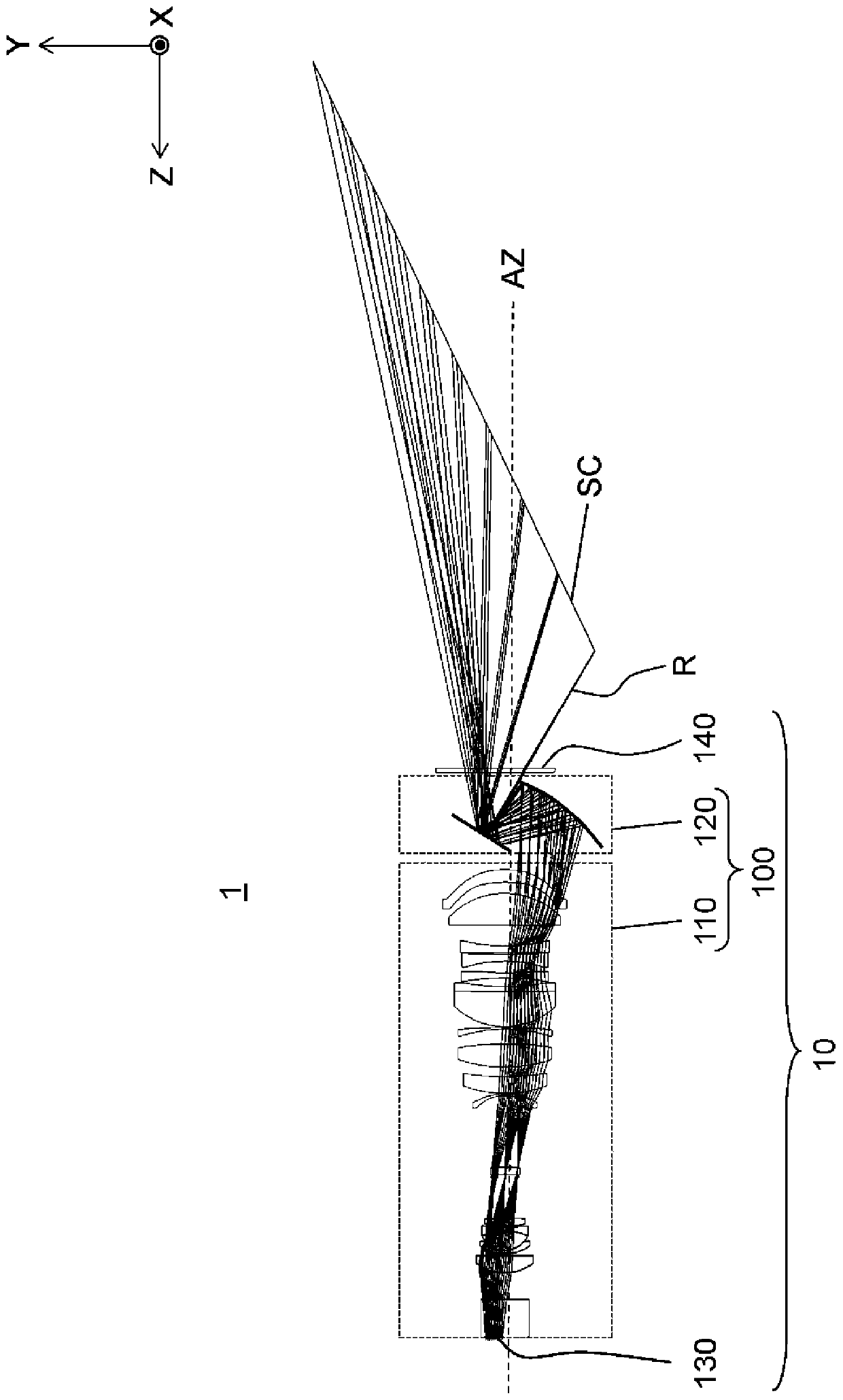
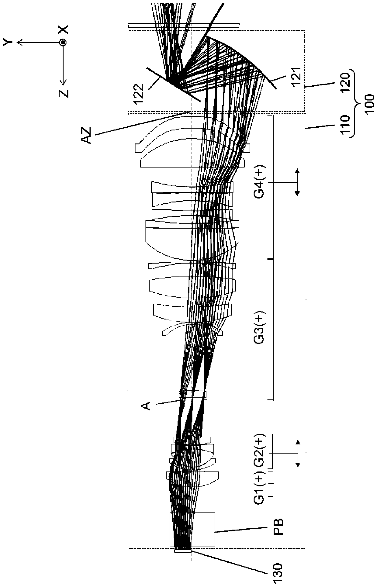
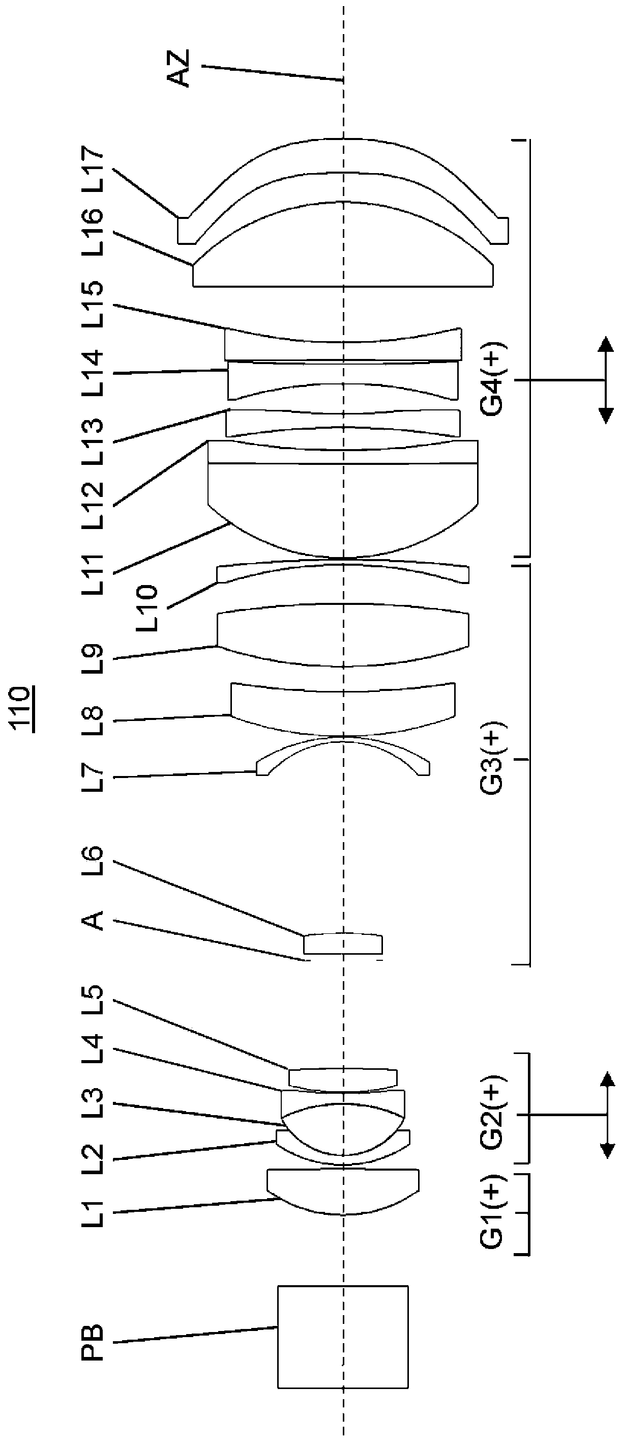
[0027] figure 1 It is a structural diagram explaining the image projection system 1 of this embodiment. The image projection system 1 includes an image projection device 10 and a screen SC (an example of a projected surface). The image projection device 10 is composed of a projection optical system 100, an image display element 130, and a transmission element 140. The projection optical system 100 includes a transmission optical system 110 and a reflection optical system 120. The image projection device 10 projects an image onto a screen SC such as a ceiling, for example. In addition, the image projection device 10 is installed, for example, inside a building, a vehicle, or the like having interior walls. The image projection device 10 according to this embodiment projects an image on a screen SC having a curvature. In additi...

Embodiment 1

[0147] The following Tables 7 to 11 show specific data of the transmission optical system 110 of Numerical Example 1. In addition, the throw ratio in Numerical Example 1 is 0.147. In addition, the projection magnification is 178.75. In addition, the size of the image display element 130 used was 9.856 mm in the long side direction and 6.162 mm in the short side direction. Figure 5 It is a structural diagram of the image projection device 10 and the screen SC in Numerical Embodiment 1. When viewed from the X direction perpendicular to the paper surface, the screen SC is arranged parallel to the optical axis AZ of the transmission optical system.

[0148] Table 7 below shows the surface data of each optical element of Numerical Example 1.

[0149] [Table 7]

[0150]

[0151]

[0152] Below, Table 8 shows aspheric surface data.

[0153] [Table 8]

[0154] coefficient Side 4 Side 5 Side 26 Side 27 Side 34 Side 35 k0.195210.00000-34.475130.000001.011140.94147 A3.5196E-055.2759E-052...

Embodiment 2

[0166] The following Tables 12 to 16 show specific data of the transmission optical system 110 of Numerical Example 2. In addition, the throw ratio in Numerical Example 2 is 0.165. In addition, the projection magnification is 178.22. In addition, the size of the image display element 130 used was 9.856 mm in the long side direction and 6.162 mm in the short side direction. Image 6 It is a structural diagram of the projection optical system 100 and the screen SC in Numerical Embodiment 2. When viewed from the X direction perpendicular to the paper surface, the screen SC is arranged to be inclined by 10 degrees with respect to the optical axis AZ of the transmission optical system.

[0167] The following Table 12 shows the surface data of each optical element of Numerical Example 2.

[0168] [Table 12]

[0169]

[0170] Below, Table 13 shows aspheric surface data.

[0171] [Table 13]

[0172] coefficient Side 4 Side 5 Side 26 Side 27 Side 34 Side 35 k0.173990.00000-24.309630.000...


PUM


Abstract

This projection optical system (100) for enlarging and projecting an image of an image display element (130) on a surface to be projected on (SC), is provided with a transmission optical system (110)and a reflection optical system (120). The transmission optical system (110) includes a plurality of lenses and an aperture diaphragm. The reflection optical system (120) includes: a first reflectionsurface which reflects emission light from the transmission optical system (110); and a second reflection surface which reflects emission light from the first reflection surface. The surface to be projected on (SC) is not parallel to the display surface of the image display element (130). The main beam of a reference beam (R) is a beam which passes through the center of the aperture diaphragm among beams projected to the nearest side of the projection optical system (100) on the surface to projected (SC). Local power on the first reflection surface at a location at which the main beam of the reference beam (R) is incident to the first reflection surface is stronger than local power on the second reflection surface at a location at which the main beam of the reference beam (R) is incident to the second reflection surface.

Description

Technical field [0001] The present disclosure relates to a projection optical system for projecting an image generated by an image display element. Background technique [0002] Patent Document 1 discloses a projection device using a projection optical system including a reflective surface. The projection optical system is a projection optical system for magnifying and projecting an image formed on a bulb on a projection surface, and includes a lens optical system, a first reflective surface, and a second reflective surface. The lens optical system includes a plurality of lenses, and has positive refractive power in order to form an intermediate image between the projection surface and the bulb. The first reflecting surface has a positive refractive power in order to reflect the diffused light beam after imaging the intermediate image to form an image on the projection surface. The second reflecting surface makes the light emitted from the lens optical system enter the first re...

Claims


Application Information

Patent Timeline
Patent Type & Authority Applications(China)
IPC IPC(8): G02B17/08G02B13/18G03B21/14
CPCG02B17/08G02B13/16G03B21/28G02B13/18
Inventor 内田恒夫山田克
Owner PANASONIC INTELLECTUAL PROPERTY MANAGEMENT CO LTD
Why Eureka
Try Eureka