Controllable guided fire extinguishing bomb and fire extinguishing system and fire extinguishing method

A technology of fire extinguishing bombs and control bins, which is applied in fire rescue and other directions, can solve the problems of delayed rescue, difficulty of fire extinguishing bombs hitting the ignition point, and firefighters not being able to clearly obtain the ignition point, so as to reduce the deviation rate and improve the fire extinguishing efficiency.

Pending Publication Date: 2019-11-19
西安恒宇众科空间技术有限公司
View PDF0 Cites 7 Cited by
  • Summary
  • Abstract
  • Description
  • Claims
  • Application Information

AI Technical Summary

Problems solved by technology

[0003] For the fire extinguishing of high-rise buildings, it is difficult for general fire trucks to reach the height of high-rise buildings. In the prior art, unmanned aerial vehicles are used to drive guided fire extinguishing bombs to extinguish fires. At the same level, the guided fire extinguishing bombs are launched, and the guided fire extinguishing bombs are injected into the fire field for fire extinguishing
However, this fire extinguishing method requires remote control by firefighters. Due to the large smoke at the fire scene, firefighters cannot clearly obtain the specific location of the fire point. Moreover, after ordinary fire extinguishing bombs are fired, it is difficult for the fire extinguishing bombs to hit the fire point because the flight angle cannot be adjusted. , unable to effectively extinguish the fire source, leading to delays in rescue, posing a great threat to life and property in the fire

Method used


Image

  • Controllable guided fire extinguishing bomb and fire extinguishing system and fire extinguishing method
  • Controllable guided fire extinguishing bomb and fire extinguishing system and fire extinguishing method
  • Controllable guided fire extinguishing bomb and fire extinguishing system and fire extinguishing method

Examples


Embodiment Construction

[0032] The present invention will be described in detail below in conjunction with the accompanying drawings and specific embodiments.

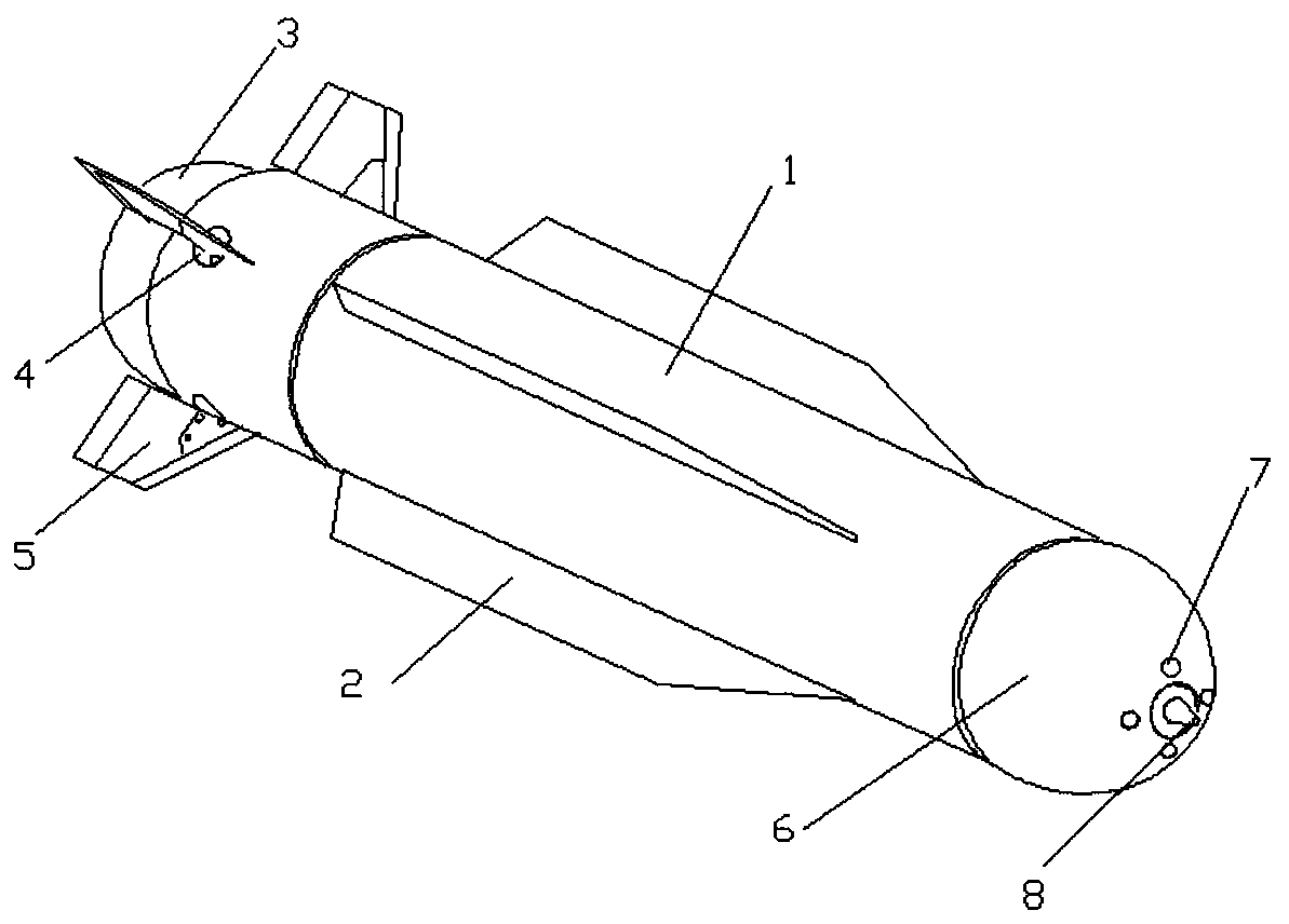
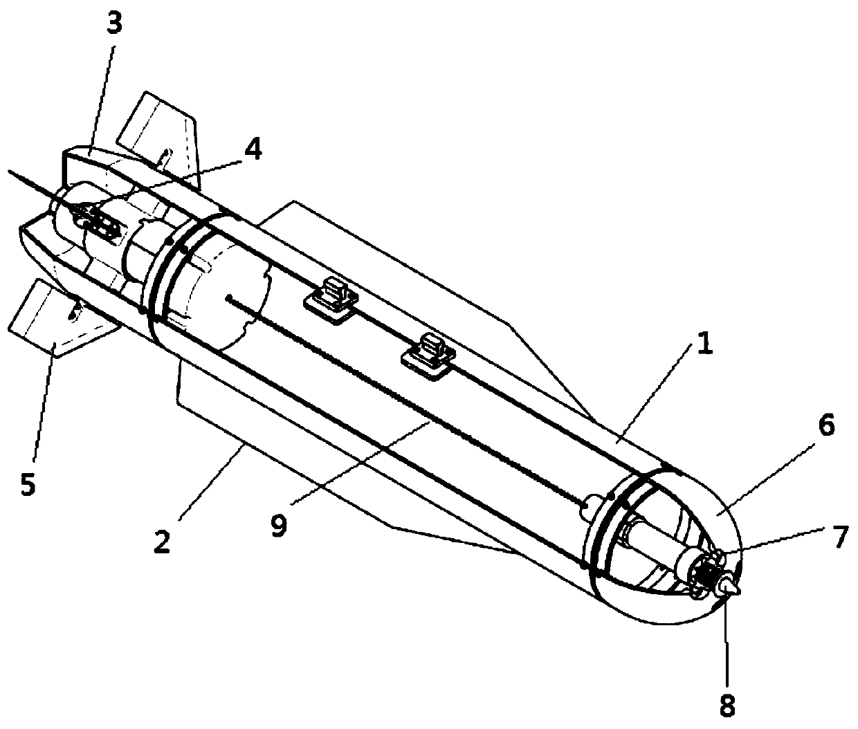
[0033] On the one hand, the embodiment of the present invention discloses a controllable guided fire extinguishing bomb, such as figure 1 As shown, the projectile body 1 is included, and the projectile body 1 is a cylindrical hollow shell, both ends of which are open, and an accommodation space for accommodating fire extinguishing powder is formed inside, and a detonating cord is arranged in the accommodation space. The detonating cord has the function of explosion. It extends from the front end to the rear end of the hollow shell, and extends out of the accommodation space from the rear end, so as to explode the hollow shell as a whole and make the fire extinguishing in the accommodation space The powder is spilled, and the fire is more fully extinguished.

[0034] The front end of projectile body 1 is connected with warhead 6, and warhead ...


PUM


Abstract

The invention provides a controllable guided fire extinguishing bomb, a fire extinguishing system and a fire extinguishing method. The controllable guided fire extinguishing bomb comprises a bomb body, wherein the front end of the bomb body is connected to a warhead; a four-quadrant seeker is arranged inside the bomb body and is used for measuring the temperature information of each orientation infront of the warhead; the rear end of the warhead is connected to a control bin; and a controller, a plurality of steering engines and a rocket engine are arranged in the control bin. The four-quadrant seeker is adopted in the controllable guided fire extinguishing bomb, so that the temperatures of the warhead in different directions can be accurately obtained, the position of an ignition point is judged according to the temperature difference; and the steering engines are controlled by the controller to adjust the orientation of a tail vane, so that the controllable guided fire extinguishingbomb flies toward the ignition point, and finally the controllable guided fire extinguishing bomb precisely extinguishes fire of the ignition point; the fire extinguishing efficiency is improved; andthe deviation rate is reduced.

Description

【Technical field】 [0001] The invention belongs to the technical field of high-rise building rescue and fire extinguishing, and in particular relates to a controllable guided fire extinguishing bomb, a fire extinguishing system and a fire extinguishing method. 【Background technique】 [0002] At present, in large and medium-sized cities, the height and density of high-rise buildings are gradually increasing, and the fire safety problems of high-rise buildings are also becoming more and more prominent. Once a fire breaks out in a high-rise building, the consequences will be disastrous. The fire fighting of high-rise buildings has become a severe test faced by various cities in the development process. [0003] For the fire extinguishing of high-rise buildings, it is difficult for general fire trucks to reach the height of high-rise buildings. In the prior art, unmanned aerial vehicles are used to drive guided fire extinguishing bombs to extinguish fires. At the same level, th...

Claims


Application Information

Patent Timeline
Patent Type & Authority Applications(China)
IPC IPC(8): A62C37/40
CPCA62C37/40
Inventor 陈昊明郭晓伟孟宪玮袁航
Owner 西安恒宇众科空间技术有限公司
Why Eureka
Try Eureka