Blanking device

A technology of blanking device and material receiving position, which is applied in the direction of transportation and packaging, conveyor objects, etc., can solve the problems of easy deformation of pins, and achieve the effects of avoiding mutual collision, realizing protection, and avoiding deformation of pins

Pending Publication Date: 2019-11-19
GREE ELECTRIC APPLIANCES CHONGQING +1
View PDF0 Cites 0 Cited by
  • Summary
  • Abstract
  • Description
  • Claims
  • Application Information

AI Technical Summary

Problems solved by technology

[0003] Based on this, it is necessary to provide a blanking device that effectively protects the pins of the power module for the problem that the pins are easily deformed during the traditional power module insertion process

Method used


Image

  • Blanking device
  • Blanking device
  • Blanking device

Examples


Embodiment Construction

[0059] In order to make the purpose, technical solution and advantages of the present invention clearer, a blanking device of the present invention will be further described in detail through the following examples and in conjunction with the accompanying drawings.

[0060] It should be noted that when an element is referred to as being “fixed” to another element, it can be directly on the other element or there can also be an intervening element. When an element is referred to as being "connected to" another element, it can be directly connected to the other element or intervening elements may also be present. In contrast, when an element is referred to as being "directly on" another element, there are no intervening elements present. The terms "vertical," "horizontal," "left," "right," and similar expressions are used herein for purposes of illustration only. Various objects in the drawings of the embodiments are drawn to a scale convenient for illustration and not to the s...


PUM


Abstract

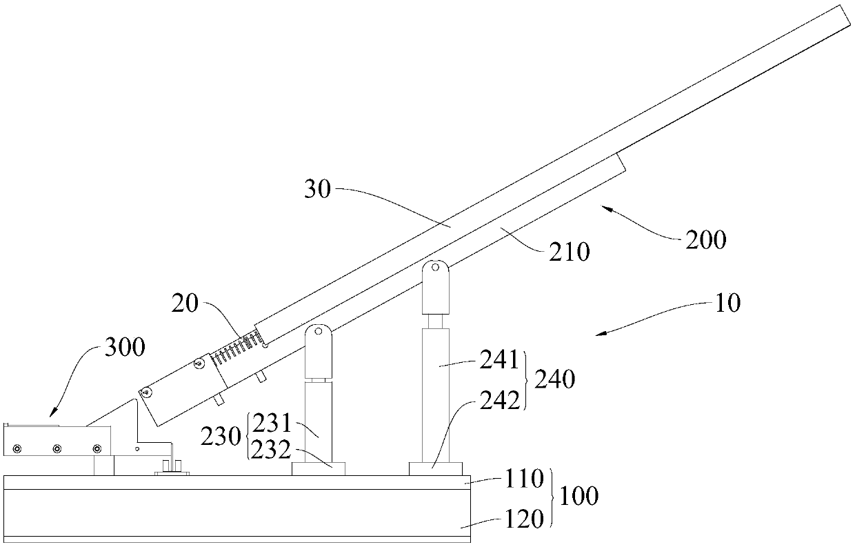
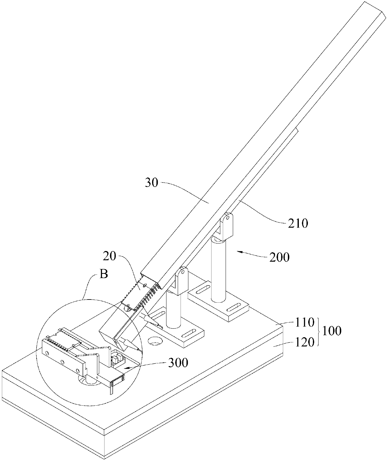
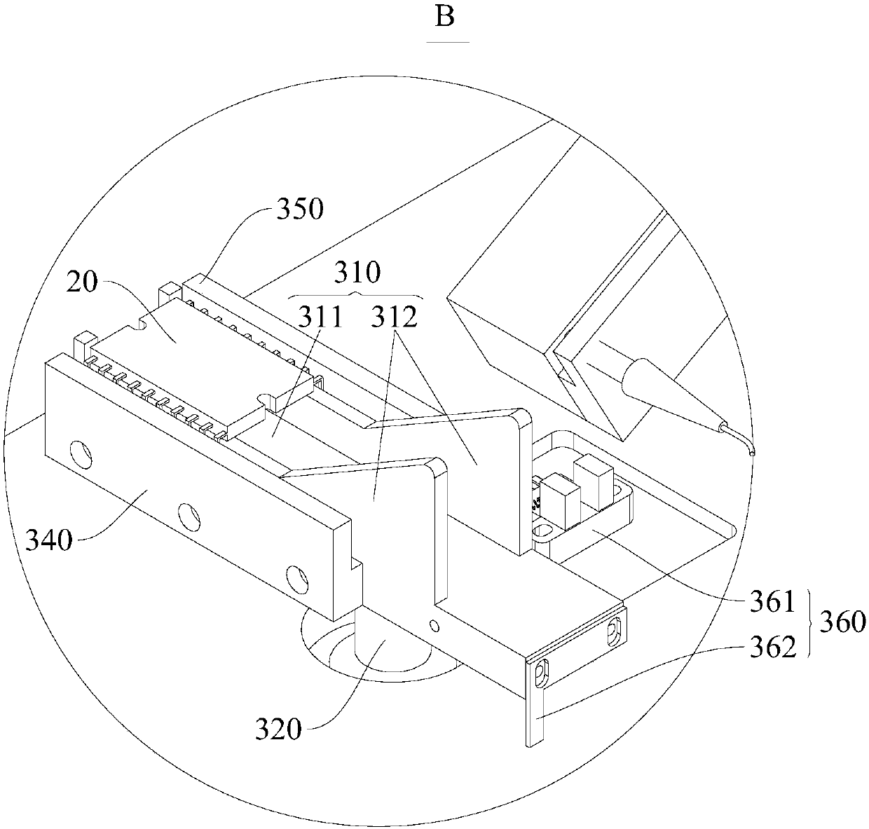
The invention relates to a blanking device which comprises a base, a feeding mechanism and a rotary table mechanism. The feeding mechanism is arranged on the base, and the feeding mechanism is used for controlling workpieces to be mounted to be fed in sequence. The rotary table mechanism is rotationally arranged on the base, and arranged at the downstream position of the feeding mechanism in the feeding direction of the feeding mechanism. The rotary table mechanism is provided with a receiving position and a conveying device. When rotary table mechanism is located at the receiving position, the rotary table mechanism receives the to-be-mounted workpieces conveyed by the feeding mechanism, and the rotary table mechanism rotates to the conveying position after receiving the to-be-mounted workpieces. According to the blanking device, sequential feeding of the to-be-mounted workpieces is achieved through the feeding mechanism, and mutual collisions between the to-be-mounted workpieces areavoided. The rotary table mechanism rotates to the conveying position after receiving the to-be-mounted workpieces at the receiving position, the to-be-mounted workpieces also rotate by a certain angle, an operator can conveniently avoid pins when takin the to-be-mounted workpieces, and the pins of the to-be-mounted workpieces are further protected. The pins of the to-be-mounted workpieces are prevented from deforming, and the quality problem in the assembling process of the to-be-mounted workpieces is reduced.

Description

technical field [0001] The invention relates to the technical field of automatic production, in particular to a blanking device. Background technique [0002] During the assembly process of the electrical box components of the air conditioner's external unit, the power module needs to be inserted into the mounting hole of the PCB, and then wave soldering is performed. The general power module incoming material is tubular. The traditional power module insertion process is to pour out the power module and place it in the electrostatic box. The operator takes out the power module in the electrostatic box and then inserts it. However, when pouring out the power module, the pins are easily deformed due to mutual collision, and the operator can only take the pins of the power module according to the direction in which the power module is poured out. and other quality defects. Contents of the invention [0003] Based on this, it is necessary to provide a blanking device that ef...

Claims


Application Information

Patent Timeline
Patent Type & Authority Applications(China)
IPC IPC(8): B65G47/04B65G47/244
CPCB65G47/04B65G47/244
Inventor 邵征锐袁长锋
Owner GREE ELECTRIC APPLIANCES CHONGQING
Why Eureka
Try Eureka