Fabricated T-shaped beam jacking auxiliary steel component

A prefabricated, steel component technology, applied in the direction of erecting/assembling bridges, bridges, bridge maintenance, etc., can solve the problems of consistency, danger, and jacks without insurance facilities, etc., to achieve the effect of improving stability and increasing stability

Pending Publication Date: 2019-11-19
JIANGXI FUHUANG STEEL STRUCTURE CO LTD
View PDF0 Cites 2 Cited by
  • Summary
  • Abstract
  • Description
  • Claims
  • Application Information

AI Technical Summary

Problems solved by technology

[0004] Aiming at the deficiencies of the prior art, the present invention provides an assembled T-beam jacking auxiliary steel member, which is provided with safety facilities to limit the position of the jack, which is not easy to slip off from the steel plate and cause danger, and the support steel plate of the jack can support the bridge without the need to The jack supports the bridge under force for a long time, and when multiple jacks are used, the jacking height of multiple jacks can be limited to be consistent. The steel plate of the support can not support the bridge, and the bridge needs to be supported by the jack for a long time, which is prone to danger during the lifting process, and when using multiple jacks, it is not easy to limit the problem that the jacking height of the jacks is consistent

Method used


Image

  • Fabricated T-shaped beam jacking auxiliary steel component
  • Fabricated T-shaped beam jacking auxiliary steel component
  • Fabricated T-shaped beam jacking auxiliary steel component

Examples


Embodiment 1

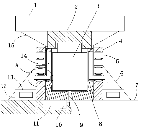
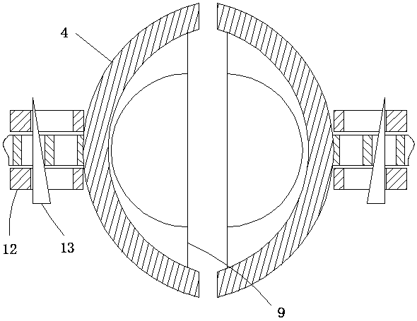
[0025] An assembled T-beam jacking auxiliary steel member, including a base 7, a top plate 1, a hydraulic cylinder 3 and two arc-shaped plates 4, the lower sides of the opposite ends of the two arc-shaped plates 4 are fixedly connected with a fixed plate 9, two The upper end of the fixed plate 9 is provided with an arc-shaped slot, the lower end of the hydraulic cylinder 3 is located in the arc-shaped slot, and the lower side of the arc-shaped plate 4 away from the fixed plate 9 is fixedly connected with a triangular plate 6, and the triangular plate 6 is connected to the base through a connecting mechanism. The upper side of 7 is connected, the lower end of the top plate 1 is fixedly connected with the installation block 2, the lower end of the installation block 2 is clamped with the upper end of the hydraulic cylinder 3 through a cylindrical groove, and the left and right sides of the lower end of the installation block 2 are fixedly connected with the limit plate 8, Limitin...

Embodiment 2

[0030] Embodiment 2: the difference based on Embodiment 1 is;

[0031] The limit mechanism includes a limit rod 21 slidingly sleeved in the limit hole 5, one end of the limit rod 21 extends into the limit groove 14, and the other end of the limit rod 21 passes through the limit hole 5 and is fixedly connected to a limited Position block 19, two arc-shaped pieces 20 are symmetrically fixedly connected on the bar wall of position-limiting rod 21, and both sides opposite in the position-limiting hole 5 are provided with draw-in grooves, and two draw-in grooves are connected with two arc-shaped pieces respectively. catch.

[0032] The limit mechanism provided in the present invention, when in use, insert the limit rod 21 into the limit hole 5, the elastic piece 20 in the limit hole 5 can cooperate with the draw-in groove to limit the limit rod 21, avoiding the use of When the limit rod 21 slides down, when the limit rod 21 is inserted in different limit holes 5, it can cooperate wi...

Embodiment 3

[0033] Embodiment 3: the difference based on embodiment 1 is;

[0034] The fixing mechanism includes an upside-down L-shaped block 18 arranged in the through groove, a rectangular opening is vertically opened at the bending part of the L-shaped block 18, and a rectangular rod 22 is slidingly sleeved in the rectangular opening. The opposite sides of the grooves are fixedly connected, the lower end of the L-shaped block 18 extends into one of the fixed grooves and has an inclined surface 23, and the corner of the vertical part of the L-shaped block 18 away from the inclined surface 23 is provided with a chamfer twenty four.

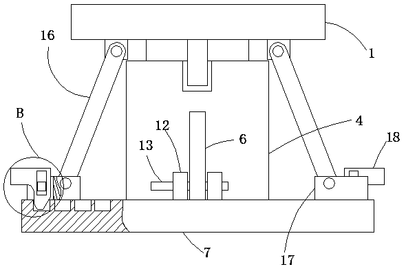
[0035] The fixing mechanism provided in the present invention, when in use, when the hydraulic cylinder 3 lifts the top plate 1, the push rod 16 swings around the pivot pin, and then the fixing block 17 slides on the base 7, and when the fixing block 17 slides, the L-shaped block 18 The inclined surface on the top slides through the fixing groove, so that ...


PUM


Abstract

The invention relates to the technical field of bridge engineering, and discloses a fabricated T-shaped beam jacking auxiliary steel component. The fabricated T-shaped beam ejecting auxiliary steel component comprises a base, a jacking plate, a hydraulic cylinder and two arc-shaped plates, wherein fixing plates are fixedly connected to the lower sides of the opposite ends of the two arc-shaped plates, arc-shaped clamping grooves are formed in the upper ends of the two fixing plates, the lower end of the hydraulic cylinder is located in the arc-shaped clamping grooves, the ends, far away from the fixing plates, of the arc-shaped plates are fixedly connected with triangular plates, the triangular plates are connected with the upper side of the base through a connecting mechanism, the lower end of a top plate is fixedly connected with a mounting block, and the lower end of the mounting block is connected with the upper end of the hydraulic cylinder through a cylindrical groove in a clamped mode. According to the fabricated T-shaped beam ejecting auxiliary steel component, the jacking can be limited by using a jack, a steel plate is difficult to slip to cause the risk, a support steelplate of the jack can support a bridge, the jack does not to stress for a long time to support the bridge, and when a plurality of jacks are used, the jacking height of the jacks can be limited to beconsistent.

Description

technical field [0001] The invention relates to the technical field of bridge engineering, in particular to an assembled T-beam jacking auxiliary steel component. Background technique [0002] At present, many highway viaducts and road bridges in China need to replace bridge supports, repair damaged supports and related accessories, and install new supports that meet the design requirements. When replacing supports, the upper structure of the bridge must be lifted to a certain level. During the bridge maintenance process, when the bridge support needs to be replaced, the bridge deck is usually supported by hydraulic jacking equipment or jacks, the old support is taken out, and the new support is put into the pier body and Between the bridge decks, at present, when the T-beam of the bridge is lifted, steel plates are added to both ends of the jack to increase the force-bearing area, but when the beam is lifted, the jack has no safety device, and it is easy to slip off the ste...

Claims


Application Information

Patent Timeline
Patent Type & Authority Applications(China)
IPC IPC(8): E01D22/00
CPCE01D22/00
Inventor 王礼本洪云峰
Owner JIANGXI FUHUANG STEEL STRUCTURE CO LTD
Why Eureka
Try Eureka