
Patsnap Eureka
For R&D, Patsnap Eureka makes reading and utilizing patents & technical documents easy.
Patsnap Eureka AIR
Designed for self-driven R&D workflows. Generate viable solutions, solve complex R&D challenges, empower your innovation with AI.

Patsnap Eureka Materials
Designed for material experts only. Revolutionize your material R&D, from search, analyze, to developing new materials.

TechResearch
Generate reliable direction feasibility study reports for your R&D in just a few steps.

TechSeek
Discover and master advanced knowledge NOW. Basics, ideas, possibilities, all at once.

TechMind
As an expert in R&D Theories, TechMind can generates customized viable solutions instantly.

TechRisk
Analyze your overall solution with one click, know your potential R&D risks in advance.

TechMonitor
Get weekly tech updates, stay abreast of the latest tech innovations and key insights.
Mounting structure for liquid crystal display television
A technology of LCD TV and installation structure, which is applied to the parts of color TV, parts of TV system, TV, etc. It can solve the problems of vertical rotation failure, inability to realize self-adaptive rotation, TV switching, etc., so as to ensure reliable and stable effect
- Summary
- Abstract
- Description
- Claims
- Application Information
AI Technical Summary
Problems solved by technology
Method used
Image

Examples
specific Embodiment
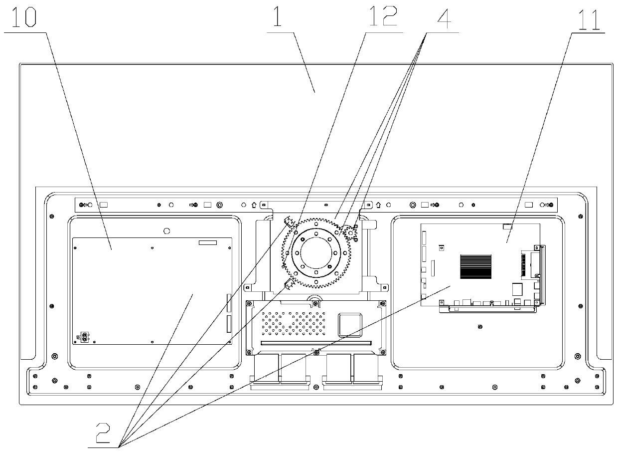
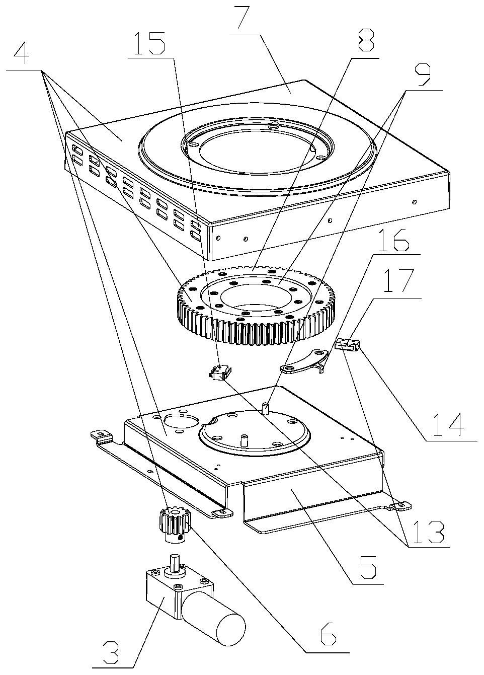
[0023] An adaptive horizontal and vertical screen display rotation mechanism for TV screen projection includes:
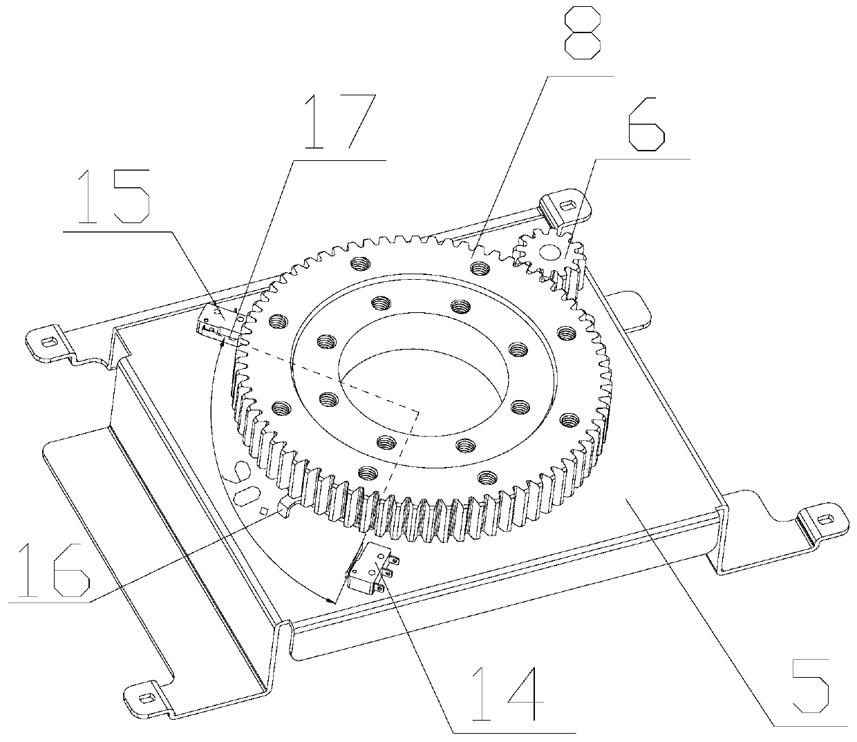
[0024] The slewing bearing, the said slewing bearing has one more ring of outer teeth and multiple screw fixing holes than ordinary bearings, the outer teeth mesh with the pinion, and the inner shaft ring of the slewing bearing is the inner ring of the above-mentioned bearing through the mounting plate one and the display The module is fastened as a whole, and the outer ring gear, that is, the above-mentioned large gear, is fixed as a whole with the wall hanging or the base through the second mounting plate;
[0025]The motor, the motor is fastened together with the display module through the mounting plate 1, and the output shaft is equipped with a pinion gear that meshes with the external teeth of the slewing support. The motor is controlled by the control circuit to realize the functions of forward rotation, reverse rotation and start-stop. The selected motor of...
Embodiment 1
[0042] The technical solutions in the embodiments of the present invention will be clearly and completely described below in conjunction with the accompanying drawings in the embodiments of the present invention. Obviously, the described embodiments are only part of the embodiments of the present invention, not all of them. Based on The embodiments of the present invention and other embodiments obtained by persons of ordinary skill in the art without creative efforts all belong to the protection scope of the present invention.
[0043] It should be noted that if there is a directional indication (such as up, down, left, right, front, back...) in the embodiment of the invention, the directional indication is only used to explain the relationship between the components in a certain posture. Relative positional relationship, movement conditions, etc., if the specific posture changes, the directional indication will also change accordingly.
[0044] The present invention relates t...
PUM
 Abstract
Description
Claims
Application Information
 - R&D Engineer
- R&D Manager
- IP Professional
- Industry Leading Data Capabilities
- Powerful AI technology
- Patent DNA Extraction
Browse by: Latest US Patents, China's latest patents, Technical Efficacy Thesaurus, Application Domain, Technology Topic, Popular Technical Reports.
© 2024 PatSnap. All rights reserved.Legal|Privacy policy|Modern Slavery Act Transparency Statement|Sitemap|About US| Contact US: help@patsnap.com