
Boiler waste heat recycling device

A boiler waste heat and furnace body technology, which is applied in lighting and heating equipment, greenhouse gas reduction, climate sustainability, etc. Contains a large amount of impurities, reduces heat loss, and improves the effect of heating

Active Publication Date: 2019-11-19
福州卓能科技有限公司
View PDF6 Cites 3 Cited by
  • Summary
  • Abstract
  • Description
  • Claims
  • Application Information

AI Technical Summary

Problems solved by technology

[0004] In the prior art, the fuel used by most boilers is coal. The smoke discharged by this boiler not only contains a large amount of heat, but also contains a large amount of dust and toxic substances. Direct discharge of gas into the air will cause a lot of pollution to the air. At the same time, the exhaust gas contains a lot of heat energy, and direct discharge will waste a lot of energy, which does not meet the requirements of energy-saving and emission-reduction development. However, common boiler waste heat recovery devices can only The heat recovery in the exhausted waste smoke achieves the effect of energy saving, but it cannot filter the dust and toxic substances in the waste smoke, which will cause air pollution and benefit the lives of surrounding residents

Method used


Image

  • Boiler waste heat recycling device
  • Boiler waste heat recycling device
  • Boiler waste heat recycling device

Examples


Embodiment Construction

[0025] The following will clearly and completely describe the technical solutions in the embodiments of the present invention with reference to the accompanying drawings in the embodiments of the present invention. Obviously, the described embodiments are only some, not all, embodiments of the present invention.

[0026] In describing the present invention, it should be understood that the terms "upper", "lower", "front", "rear", "left", "right", "top", "bottom", "inner", " The orientation or positional relationship indicated by "outside", etc. is based on the orientation or positional relationship shown in the drawings, and is only for the convenience of describing the present invention and simplifying the description, rather than indicating or implying that the referred device or element must have a specific orientation, so as to Specific orientation configurations and operations, therefore, are not to be construed as limitations on the invention.

[0027] refer to Figure ...


PUM


Abstract

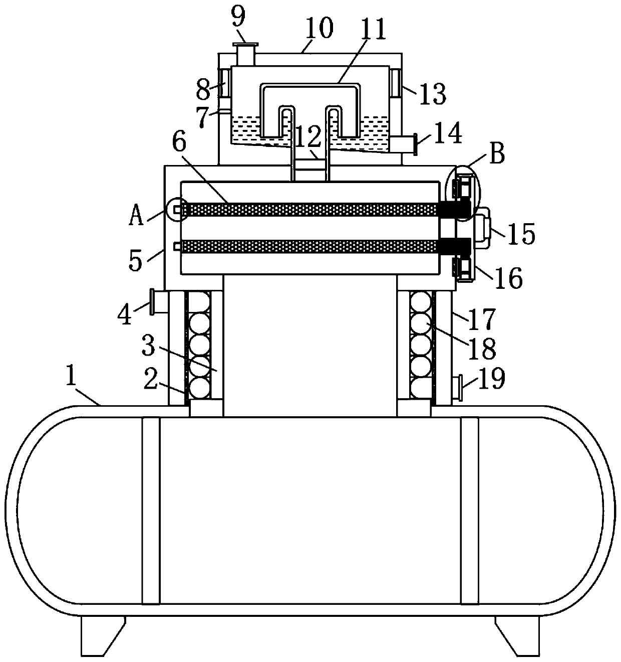
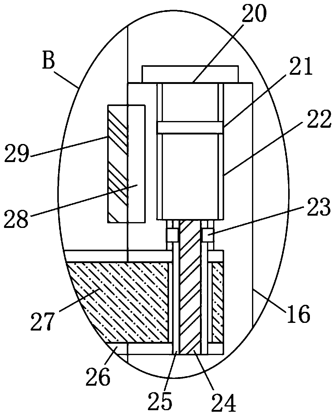
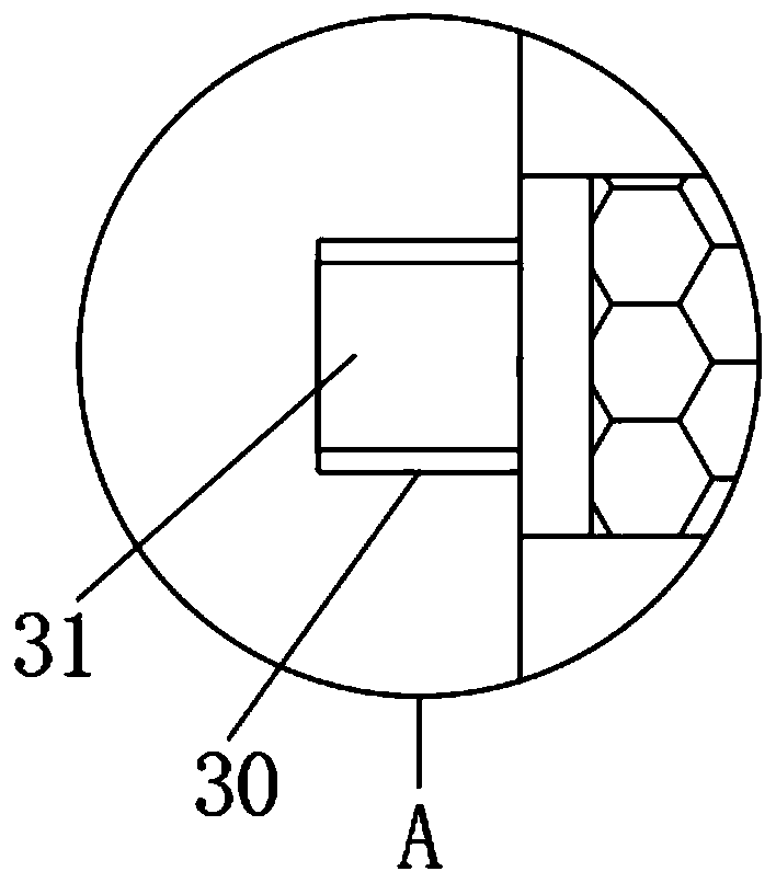
The invention discloses a boiler waste heat recycling device. The boiler waste heat recycling device comprises a boiler body, wherein a smoke discarding end of the boiler body is fixedly connected toa smoke discharging pipe; a water pipe is arranged at the outer side of the smoke discharging pipe in a sleeving manner; the upper side of the boiler body is fixedly connected to a heat insulating plate; a heat insulating layer is arranged at the inner side of the heat insulating plate; the left side of the water pipe is a water inlet; the right side of the water pipe is a water outlet; the waterinlet and the water outlet penetrate through the heat insulating plate and extend to the exterior of the heat insulating plate; the upper side of the heat insulating plate is fixedly connected to a filter box; the lower side of the filter box communicates with the smoke discharging pipe; two installing holes are formed in the right side of the filter box; and a fixing plate is arranged at the right side of the filter box. The boiler waste heat recycling device has reasonable structure design; the water pipe is of a spiral structure; the effect of pure water heating is improved; the heat contained in exhaust gas is fully utilized; and the exhaust gas can be filtered multiple times so as to ensure the emission of the exhaust gas without affecting the life of surrounding residents.

Description

technical field [0001] The invention relates to the technical field of waste heat recovery and utilization, in particular to a boiler waste heat recovery and utilization device. Background technique [0002] The boiler is a kind of energy conversion equipment. The energy input to the boiler includes chemical energy and electric energy in the fuel, and the boiler outputs steam, high-temperature water or organic heat carrier with a certain amount of heat energy. [0003] The original meaning of the pot refers to the water container heated on the fire, and the furnace refers to the place where fuel is burned. The boiler includes two parts: the pot and the furnace. The hot water or steam generated in the boiler can directly provide the required heat energy for industrial production and people's life, and can also be converted into mechanical energy through a steam power device, or converted into electrical energy through a generator. Boilers that provide hot water are called ho...

Claims


Application Information

Patent Timeline
Patent Type & Authority Applications(China)
IPC IPC(8): F23J15/00F23J15/06F23J15/02F23J15/04
CPCF23J15/006F23J15/025F23J15/04F23J15/06F23J2217/10F23J2217/50Y02E20/30
Inventor 李升段小勇高小龙
Owner 福州卓能科技有限公司
Learn More