

Radar ranging method, device and terminal device
A radar ranging and radar technology is applied in the field of devices and terminal equipment, and radar ranging methods, and can solve the problems of inaccurate radar ranging.
- Summary
- Abstract
- Description
- Claims
- Application Information
AI Technical Summary
Problems solved by technology
Method used
Image

Examples
Embodiment 1
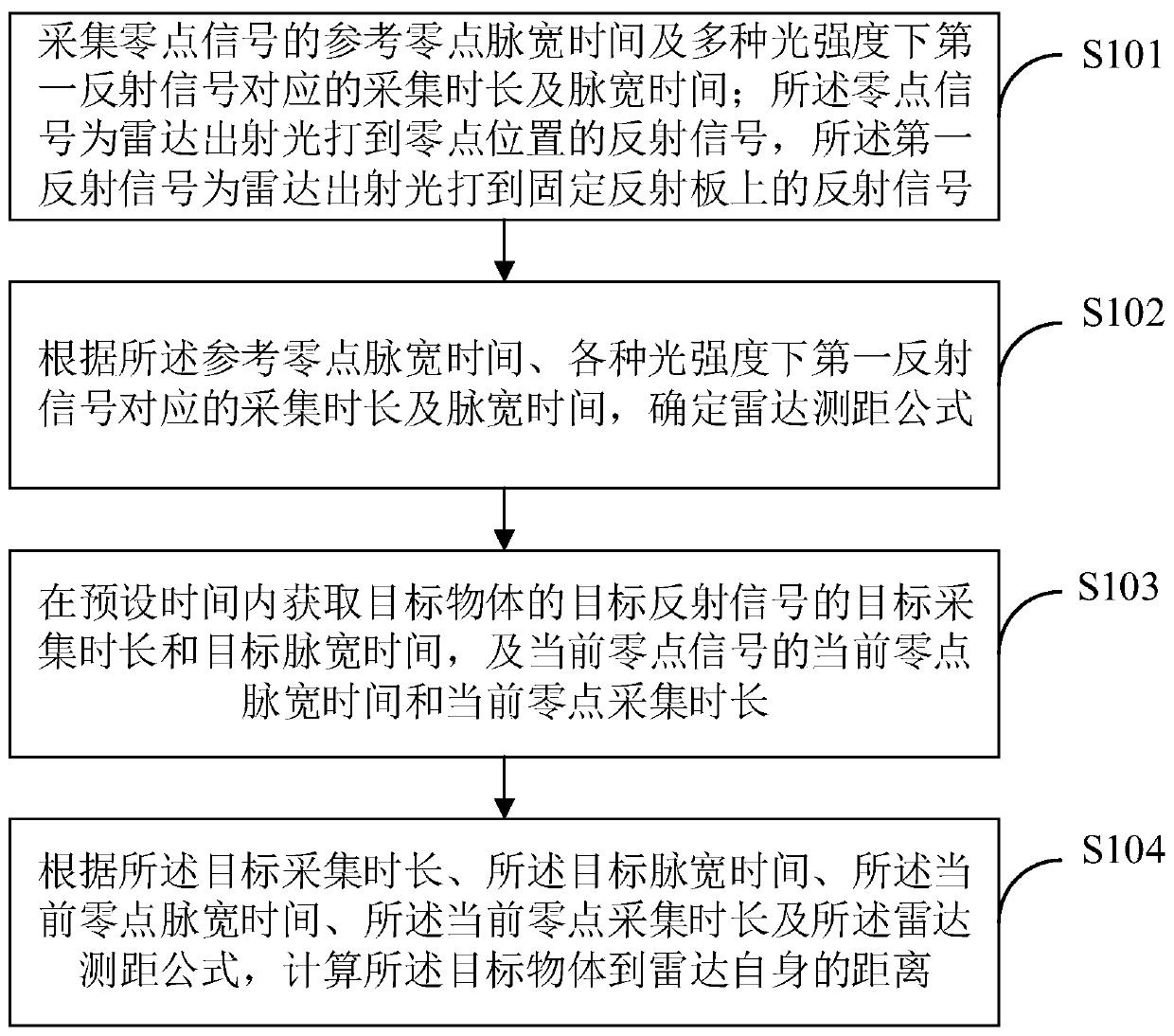
[0033] figure 1 It shows the implementation flow chart of the radar ranging method provided by an embodiment of the present invention. The main body of the process in this embodiment is radar. For the convenience of description, only the parts related to the embodiment of the present invention are shown. The details are as follows:
[0034] Such as figure 1 As shown, a radar ranging method provided in an embodiment of the present invention, the process is described in detail as follows:
[0035] S101: Collect the reference zero point pulse width time of the zero point signal and the corresponding collection duration and pulse width time of the first reflected signal under various light intensities; the zero point signal is the reflected signal of the radar emitted light hitting the zero point position, and the first reflected signal The reflected signal is the reflected signal of the radar emitted light hitting the fixed reflector.
[0036] In this example, Figure 6 shows ...
PUM
 Abstract
Description
Claims
Application Information