
Line end network adapter and network adapter structure

An adapter and network technology, applied in the direction of connection, parts of connection devices, electrical components, etc., can solve the problems of difficult maintenance, cost increase, system structure load and other problems in the later stage, and achieve compact structure, increase manufacturing and use costs, To achieve the effect of compatible join

Pending Publication Date: 2019-11-19
深圳市盛格纳电子有限公司
View PDF0 Cites 0 Cited by
  • Summary
  • Abstract
  • Description
  • Claims
  • Application Information

AI Technical Summary

Problems solved by technology

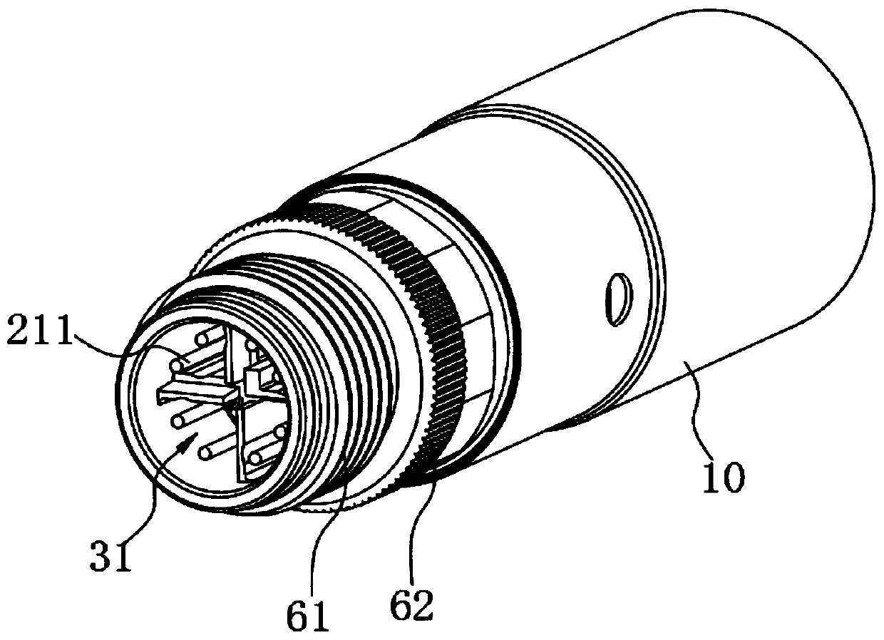
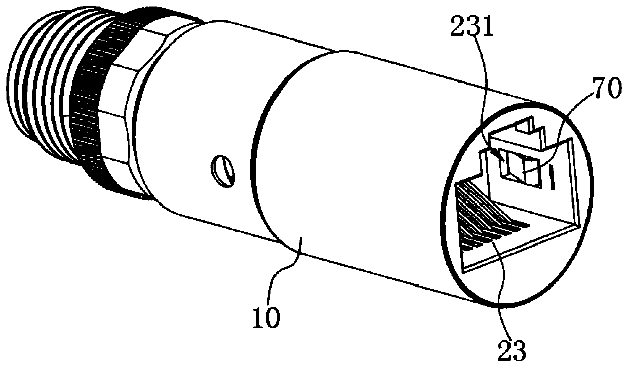
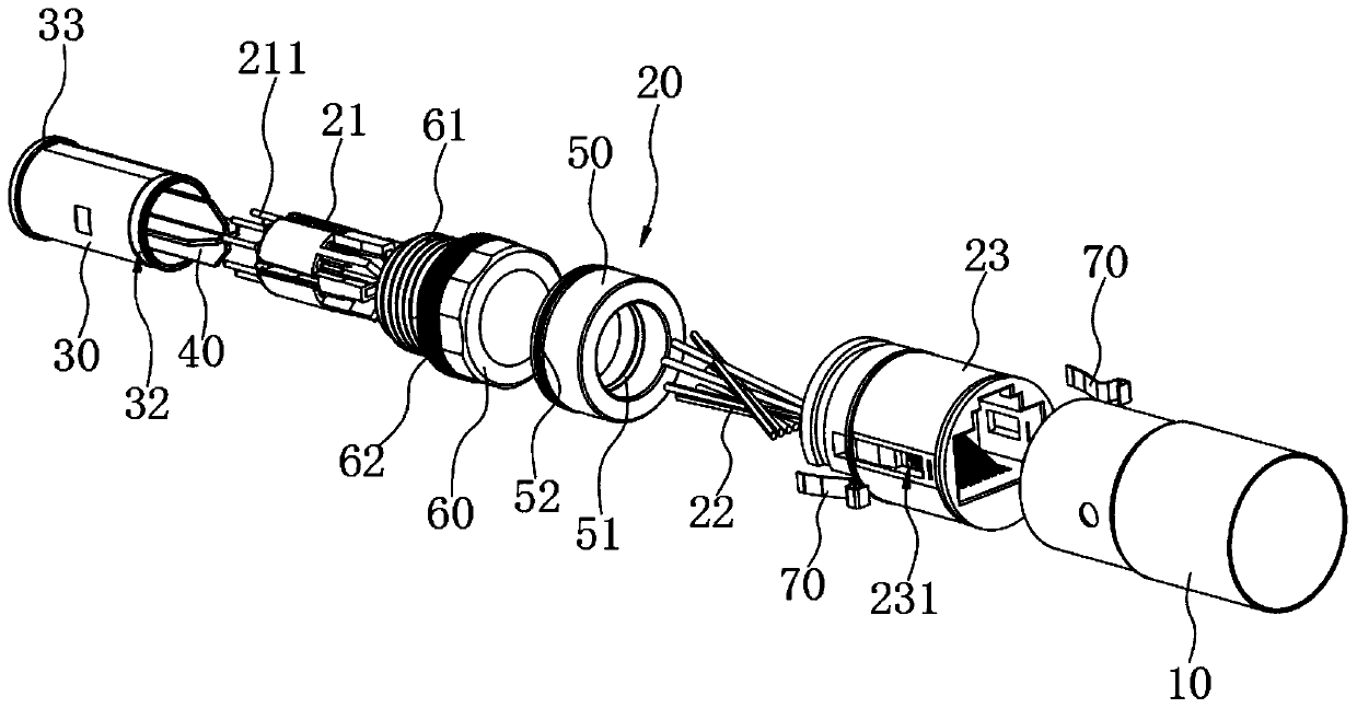
[0003] The purpose of the present invention is to provide a line-end network adapter and network adapter structure, aiming to solve the problems of increased cost, system structure load, and difficulty in later maintenance due to the addition of signal conversion systems in the prior art

Method used


Image

  • Line end network adapter and network adapter structure
  • Line end network adapter and network adapter structure
  • Line end network adapter and network adapter structure

Examples


Embodiment Construction

[0023] In order to facilitate the understanding of the present invention, the present invention will be described more fully below with reference to the associated drawings. Preferred embodiments of the invention are shown in the accompanying drawings. However, the present invention is capable of being implemented in many different forms and is not limited to the embodiments described herein. On the contrary, these embodiments are provided to make the understanding of the disclosure of the present invention more thorough and comprehensive.

[0024] It should be noted that when an element is referred to as being “fixed” to another element, it can be directly on the other element or there can also be an intervening element. When an element is referred to as being "connected to" another element, it can be directly connected to the other element or intervening elements may also be present. The terms "vertical," "horizontal," "left," "right," and similar expressions are used here...


PUM


Abstract

The invention relates to a line end network adapter and a network adapter structure. The line end network adapter comprises a hollow adapter housing with two open ends; and a signal transmission component including an Ethernet connector, an electronic wire, and a communication connector which are successively arranged in the adapter housing, wherein the Ethernet connector is electrically connectedto the communication connector through the electronic wire. The Ethernet connector can be connected to a device in operation by using an Ethernet network signal at one end, and the communication connector can be connected to a device in operation by using a communication network signal at the other end, thereby enabling direct and efficient conversion from an Ethernet network into a communicationnetwork and the compatible connection of different devices, and strengthening network integration. Moreover, due to the high degree of integration and the compact structure of the line end network adapter, the manufacturing cost is not increased, the installation space of a PC line board end is not occupied, and the complicated signal sources can be reduced, so that a device group constitutes a communication system that satisfies the cat-5e Class transmission standard requirements.

Description

technical field [0001] The invention relates to the technical field of network switching devices, in particular to a line-end network switching joint and a network switching structure. Background technique [0002] At present, information processing systems used in fields such as satellite communications and computers are usually composed of different signal devices connected. The signal cables of different signal devices are usually connected in series using M12 connectors. However, when the network standards required by different signal devices are different, the M12 connectors cannot realize direct conversion of different networks, but need to be connected on the PC board. Adding a signal conversion system in a limited space will not only increase the cost of manufacturing and use, but also complicate the system structure, making later maintenance difficult. Contents of the invention [0003] The purpose of the present invention is to provide a line-end network adapter...

Claims


Application Information

Patent Timeline
Patent Type & Authority Applications(China)
IPC IPC(8): H01R13/502H01R13/6581H01R31/06
CPCH01R31/06H01R13/502H01R13/6581
Inventor 黄彪张平辉陈荣波
Owner 深圳市盛格纳电子有限公司
Learn More