Pipe bending device

A pipe bending equipment and pipe bending technology, applied in the field of pipe bending equipment, can solve problems such as poor processing stability, and achieve the effects of preventing offset, consistent and stable curvature radius, and accurate positioning

Pending Publication Date: 2019-11-22
青岛常蒸蒸发器科技有限公司
View PDF0 Cites 0 Cited by
  • Summary
  • Abstract
  • Description
  • Claims
  • Application Information

AI Technical Summary

Problems solved by technology

[0004] Aiming at the technical problem of poor processing stability in the prior art, the purpose of the present invention is to provide a pipe bending equipment

Method used


Image

  • Pipe bending device
  • Pipe bending device
  • Pipe bending device

Examples


Embodiment Construction

[0025] Further illustrate the present invention below in conjunction with accompanying drawing.

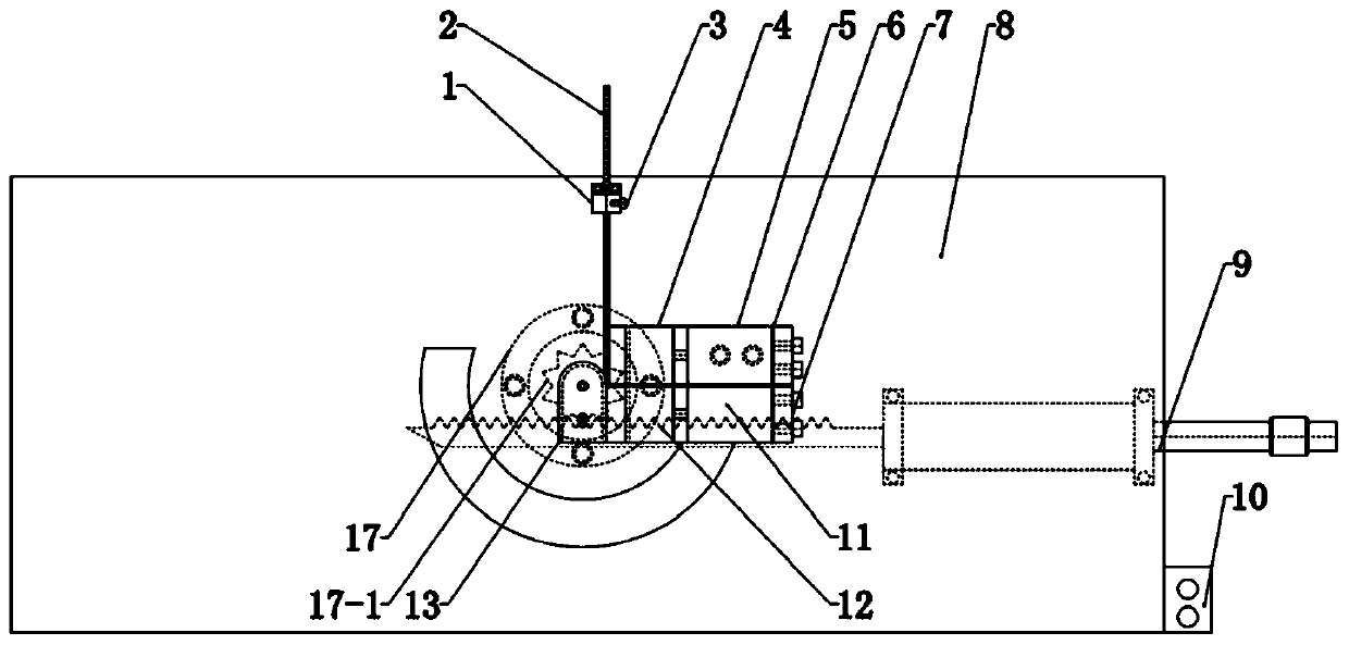
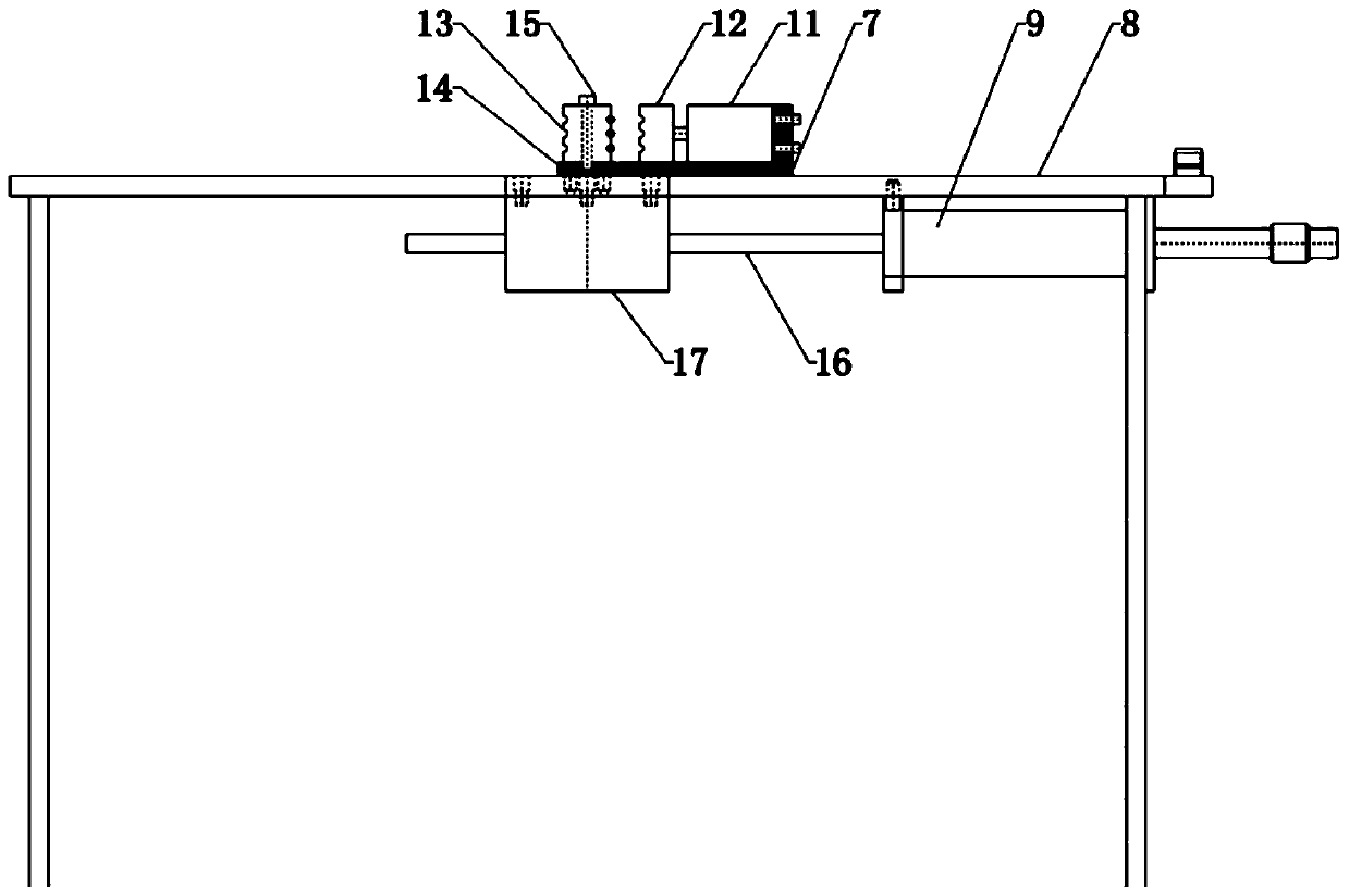
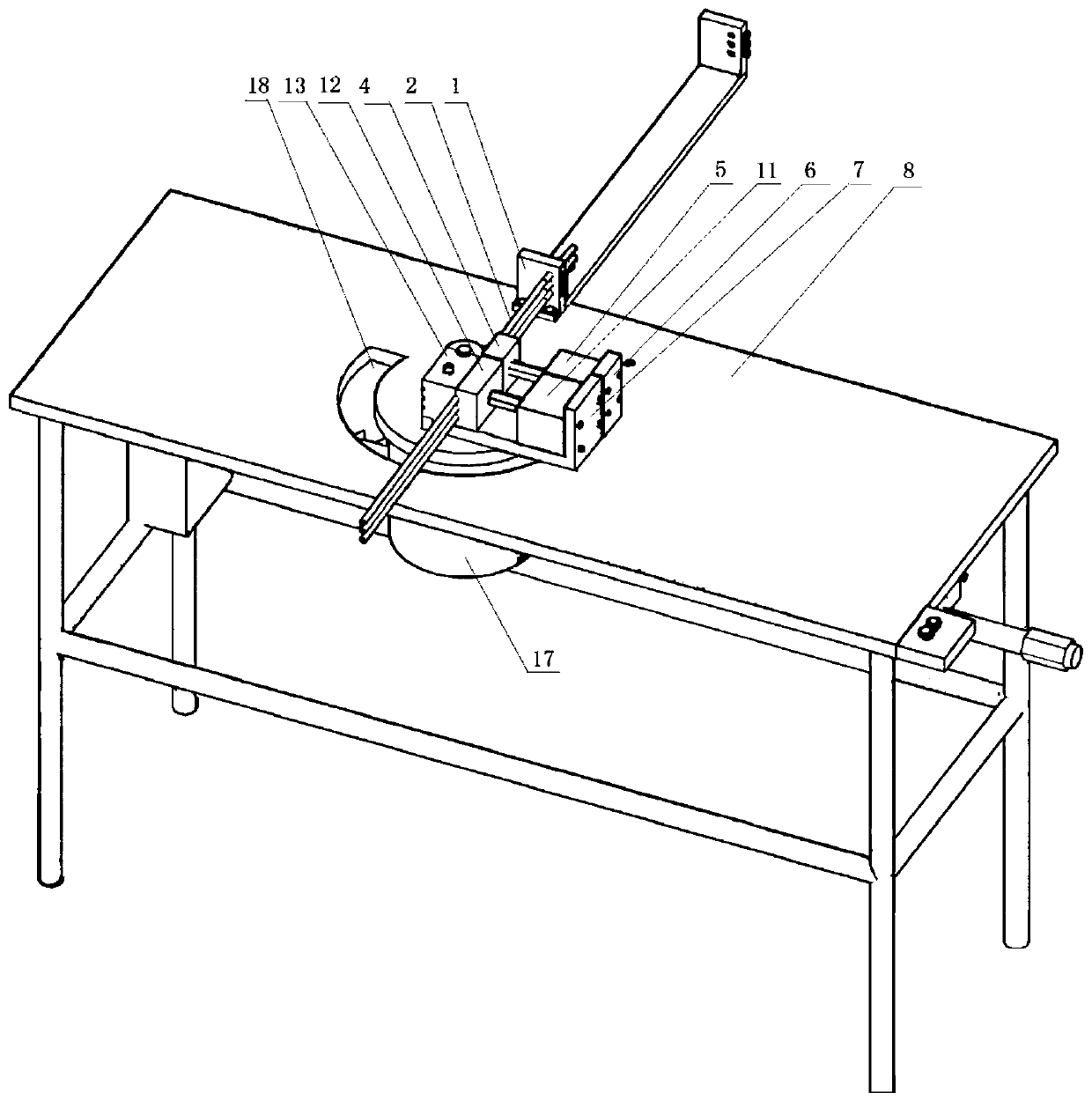
[0026] Such as figure 1 , figure 2 with image 3 As shown, a pipe bending equipment includes a support mechanism, the support mechanism includes a support column and a worktable 8 installed on it, and the workbench 8 is sequentially provided with a pipe bending mold, a clamping mechanism, a positioning mechanism, and a pipe bending mold Installed below the table top of the workbench 8, the clamping mechanism and the positioning mechanism are installed above the table top of the workbench 8,

[0027] Described pipe bending mold comprises pipe bending guide wheel 13, gear bar 16, gear 17-1, and pipe bending guide wheel 13 is installed on the workbench 8 by R mold base 14, and the central position of penetrating pipe bending guide wheel 13 is provided with screw rod 15. The curved pipe guide wheel 13 is connected with the gear 17-1 through the screw rod 15, and the gear 17-1 and ...


PUM


Abstract

The invention discloses a pipe bending device. A workbench is sequentially provided with a pipe bending mold, a clamping mechanism and a positioning mechanism; a pipe bending guiding wheel of the pipebending mold is installed on the workbench through an R mold base; a screw penetrates through the center position of the pipe bending guiding wheel to be arranged; the pipe bending guiding wheel is connected with a gear through the screw; the gear is engaged with a rack, so that the pipe bending guiding wheel is synchronously driven to rotate; a front clamping plate of the clamping mechanism andthe pipe bending guiding wheel are oppositely arranged; the front clamping plate is connected with a piston rod of a front clamping plate cylinder; the front clamping plate cylinder is used for driving the front clamping plate to move relative to the pipe bending guiding wheel; and a rear clamping plate cylinder of the positioning mechanism drives a rear clamping plate to move relative to a core rod. The pipe bending mold is matched with the core rod, and has high and wide applicability to a core rod material, the bending angle, the force degree and the shape of the pipe bending mold on the core rod can meet the requirement of sufficient consistency, and the finished product rate is greatly increased; and it is guaranteed that the curvature radius of each time of pipe bending is consistentand stable, and then it is guaranteed that after product bending, the pressing flattening rate meets the requirement.

Description

technical field [0001] The invention belongs to the technical field of pipe bending equipment, and in particular relates to a pipe bending equipment. Background technique [0002] The bent pipe is bent with a complete set of bending dies. The bending radius depends on the material properties, bending angle, the allowable amount of thinning on the outside of the bent pipe wall, the size of the inner wrinkle, and the size of the ellipticity of the bend. The current pipe bending method is generally difficult to apply to thin-walled small-radius core rod pipes. In the prior art, corresponding bending dies are provided on the workbench, and the mandrel to be bent is placed in a corresponding position, and the operator manually performs the pipe bending operation. It has the following technical problems: 1. The operation efficiency is low, time-consuming and labor-intensive, and the labor cost is high. 2. The section of the bent pipe fittings will be excessively deformed, or the...

Claims


Application Information

Patent Timeline
Patent Type & Authority Applications(China)
IPC IPC(8): B21D9/04B21D9/07B21D9/16
CPCB21D9/04B21D9/073B21D9/16
Inventor 朱金达贾影李炳涛
Owner 青岛常蒸蒸发器科技有限公司
Why Eureka
Try Eureka