Machine tool spindle assembly and machining equipment

A technology for machine tool spindles and components, applied in metal processing equipment, metal processing mechanical parts, manufacturing tools, etc., can solve problems such as loud noise, high manufacturing cost, and impact on spindle operation, and achieve convenient maintenance, simple structure, and low cost. Effect

Pending Publication Date: 2019-11-22
深圳中科创新精密科技有限公司
View PDF0 Cites 0 Cited by
  • Summary
  • Abstract
  • Description
  • Claims
  • Application Information

AI Technical Summary

Problems solved by technology

In order to realize the above water outlet structure of the main shaft core, the upper end of the shaft core must be equipped with a pulley, and the shaft core of the main shaft is driven to rotate by means of a belt connected to the motor, so as to use the space at the upper end of the shaft core to install the connecting device to connect the external high-pressure cooling water. However, when the speed exceeds a certain speed (8000 revolutions per minute), there will be difficult physical phenomena such as vibration and noise that are difficult to solve in this way of using belt linkage. Therefore, using this linkage machine tool can only be performed at low speed For low-torque and low-efficiency machine tools, in order to achieve high speed (more than 8000 rpm) in the existing technology, the machine tool must adopt a transmission mechanism in which the spindle core and the motor are directly linked, but this direct linkage mechanism must realize the spindle center. The structure and production process of the high-pressure water outlet function are very complicated and the manufacturing cost is also very high, which greatly restricts the development of high-precision and high-efficiency machine tools that require the high-pressure water outlet function in the spindle center. Once the cooling water leaks, the operation of the entire spindle will be affected or even damaged, and it may affect the risk of damage to other parts in the spindle box of the entire machine tool

Method used


Image

  • Machine tool spindle assembly and machining equipment
  • Machine tool spindle assembly and machining equipment
  • Machine tool spindle assembly and machining equipment

Examples


Embodiment Construction

[0017] The embodiments of the present invention will be described in detail below with reference to the accompanying drawings, but the present invention can be implemented in many different ways defined and covered by the claims.

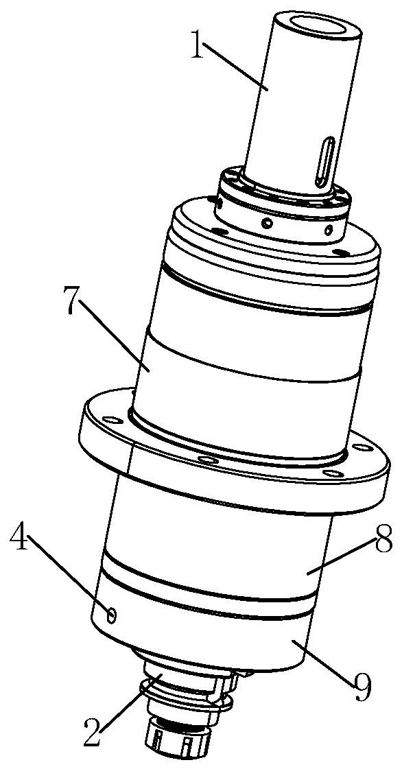
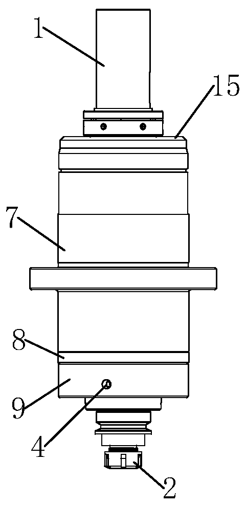
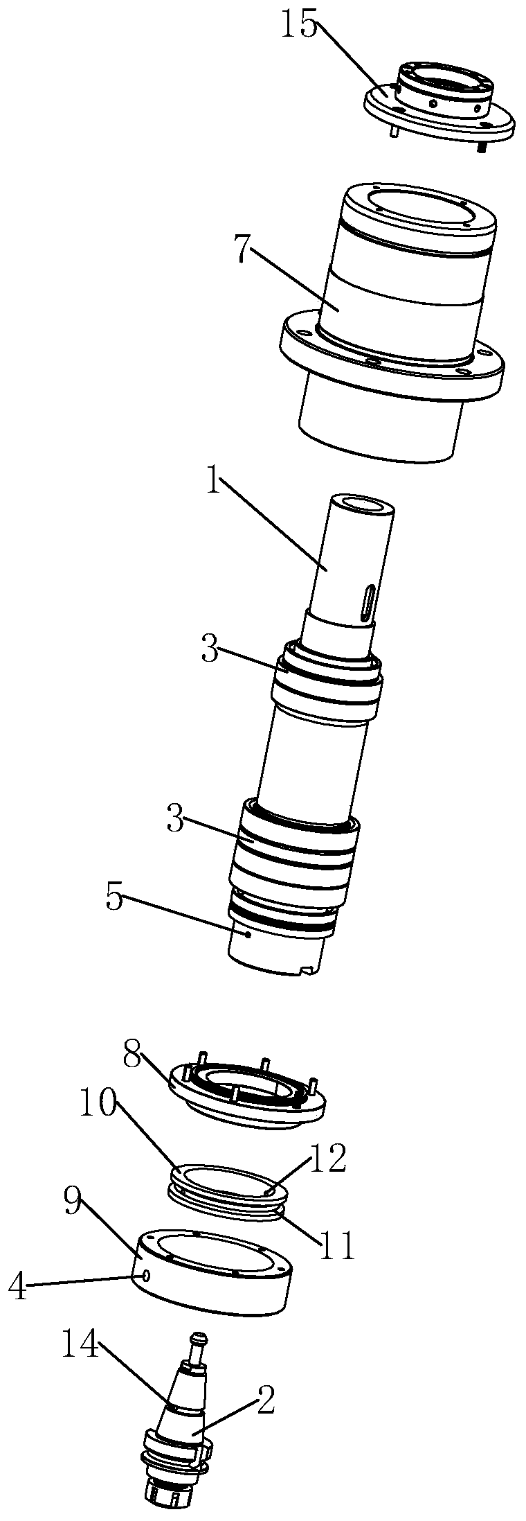
[0018] One aspect of the present invention provides a machine tool spindle assembly, including: a shaft core 1, a housing and a tool handle seat 2, the shaft core 1 is arranged in the housing through a bearing 3, and the tool handle seat 2 is connected to the tool handle seat 2 One end of the shaft core 1 is connected, and a first sealed cavity and a second sealed cavity are formed between the shell and the handle seat 2, and the shell corresponds to the side wall of the first sealed cavity A first water inlet hole 4 is opened, and a second water inlet hole 5 is opened on the shaft core 1 corresponding to the first sealed cavity and the second sealed cavity, and the first water inlet hole 4 passes through the first sealed cavity. The sealed cavity, ...


PUM


Abstract

The invention provides a machine tool spindle assembly and machining equipment. The machine tool spindle assembly comprises a shaft core, a shell and a knife handle. The shaft core is arranged in theshell through a bearing, a knife handle base is connected to one end of the shaft core, and a first sealing cavity and a second sealing cavity are formed between the shell and the knife handle in sequence. The shaft core is rotationally arranged in the shell through the bearing, a first water inlet hole is formed in the front end of the shell and corresponds to the side wall of the first sealing cavity, and a knife handle base water inlet hole is formed in the knife handle base and communicates with the first water inlet hole, the first sealing cavity, the second sealing cavity and a cooling channel in the knife handle base. According to the machine tool spindle assembly and the machining equipment, the cooling water is directly fed into the cooling channel of the knife handle base from the lower end of a spindle through the first water inlet hole formed in the shell. Therefore, various defects caused by the structure of driving a shaft core to rotate by connection of a belt and a motor or other linkage modes according to a traditional mode of feeding water at the upper end of the spindle are effectively overcome. The machine tool spindle assembly has the characteristics of being simple in structure, low in cost, and more convenient to maintain.

Description

technical field [0001] The invention relates to the technical field of machine tools, in particular to a machine tool spindle assembly and machining equipment. Background technique [0002] In the prior art, in order to improve the production efficiency of the machine tool in the process of deep hole machining, it is necessary to realize the function of high-pressure water outlet from the cooling channel of the deep hole drilling tool to reduce the high temperature generated during machining and perform rapid chip removal. The existing machine tool realizes In order to simplify the structure and cost, the high-pressure water outlet function technology of the cooling channel of deep-hole drilling tools can only install a rotating connection device on the upper end of the shaft core of the main shaft to connect with the external water inlet device, so that the high-pressure cooling water enters the inner through hole of the shaft core, and then It enters the internal through h...

Claims


Application Information

Patent Timeline
Patent Type & Authority Applications(China)
IPC IPC(8): B23B19/02
CPCB23Q1/70
Inventor 覃统
Owner 深圳中科创新精密科技有限公司
Why Eureka
Try Eureka